PLC Controller Wiring Diagram: A Step-by-Step Guide for Beginners
Sure, here's a summary of the PLC (Programmable Logic Controller) wiring diagram for beginners:1. **Understanding the Basics**: Before we start, it's important to understand what a PLC is and how it works. A PLC is a device that can be programmed to perform specific tasks based on inputs from sensors or other devices. It's like a computer in disguise, but designed specifically for industrial applications.2. **Choosing the Right PLC**: When choosing a PLC, consider factors such as the type of application, the number of inputs and outputs needed, and the programming language.3. **Connecting the PLC to the Control System**: Once you have your PLC, connect it to the control system using appropriate cables and connections. This may involve connecting the PLC to a power source, an input/output module, and any other necessary components.4. **Programming the PLC**: The programming phase involves writing instructions for the PLC to follow based on inputs from sensors or other devices. This can be done using various programming languages, such as ladder logic or structured text.5. **Testing the PLC**: After programming, it's important to test the PLC to ensure that it's working correctly and performing the intended functions. This may involve setting up simulations or conducting actual tests in a controlled environment.6. **Maintenance and Troubleshooting**: Finally, it's important to regularly maintain and troubleshoot the PLC to ensure its continued reliability and effectiveness. This may involve checking for any signs of wear and tear, updating software, or addressing any issues that arise during operation.
Dear all,
I hope this message finds you well. Today, I am excited to share with you a comprehensive guide on how to properly wire up your PLC controller. As a seasoned expert in the field of automation, I have seen it all and have developed a keen eye for detail that ensures seamless operation.
Firstly, let's start by understanding what a PLC controller is. It stands for Programmable Logic Controller, which is an essential component in modern industrial settings. It is a device that can be programmed to perform specific tasks based on inputs from various sensors and actuators. Its primary function is to manage and control the flow of data within a system, ensuring smooth operation and efficiency.
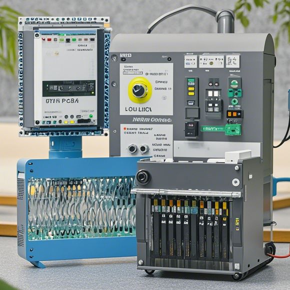
Now, back to our topic. The first step in wiring up a PLC controller is to understand its components. There are several key components, including the CPU, input/output modules, and communication interfaces. Each component plays a crucial role in ensuring the proper functioning of the system.

The CPU (Central Processing Unit) is the brain of the PLC. It processes and executes instructions from the program code stored in the memory. The CPU is responsible for managing the flow of data between the different components of the system.
Next, we have the input/output modules. These modules are responsible for receiving and processing inputs from external devices such as sensors and actuators. They also output data to these devices, enabling them to perform their functions.
Finally, we have the communication interfaces. These interfaces allow the PLC to communicate with other devices in the system. They enable the exchange of data between the PLC and other components, ensuring smooth operation.
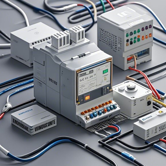
Now, let's get into the details of wiring up the PLC controller. Firstly, connect the power supply to the PLC controller. Ensure that the correct voltage and current are being supplied to the controller, as this will affect its performance.

Next, connect the CPU module to the PLC controller. This involves connecting the appropriate pins on the CPU module to the corresponding pins on the PLC controller. Make sure to follow the manufacturer's guidelines carefully, as improper connections can cause errors or even damage to the system.
Once the CPU module is connected, connect the input/output modules to the PLC controller. Again, follow the manufacturer's guidelines carefully, as improper connections can affect the functionality of the system.
Finally, connect the communication interfaces to the PLC controller. This involves connecting the appropriate pins on the communication interfaces to the corresponding pins on the PLC controller. Again, make sure to follow the manufacturer's guidelines carefully, as improper connections can cause errors or even damage to the system.
Once all the components are connected, test the system to ensure that everything is working correctly. Check for any errors or issues that may arise during testing. If any problems are found, troubleshoot them accordingly and adjust the connections accordingly.

In conclusion, wiring up a PLC controller requires careful attention to detail. By following the above steps and guidelines, you can ensure that your system is properly connected and functioning. Remember, proper wiring is crucial for the smooth operation of your PLC controller, so take your time and do not rush through this process. With practice and experience, you will become an expert at wiring up PLC controllers and enjoy the benefits they offer.
Content expansion reading:
Articles related to the knowledge points of this article:
How to Use a PLC Controller for Your Business
PLC (Programmable Logic Controller) Control System Basics
Plumbers Rule! The Role of PLC Controllers in the World of Waterworks
Connecting a PLC Controller to Your Computer
PLC Controllers: A Comprehensive Guide to Understanding Their Prices