PLC Input Output (I/O) Wiring Diagram
As a foreign trade operation, understanding the intricacies of our industrial control system is crucial. The PLC (Programmable Logic Controller) is a cornerstone of modern manufacturing and automation, providing precise control over various processes. To ensure seamless communication between the different components of your production line, it's essential to have a clear understanding of the PLC input output (I/O) wiring diagram.
At its core, an I/O wiring diagram is a visual representation of the electrical connections between the PLC and its peripheral devices. It serves as a blueprint for ensuring that all inputs and outputs are properly connected, preventing data loss or corruption during critical operations. In this guide, we'll delve into the key aspects of the I/O wiring diagram, highlighting the importance of each component and explaining how they work together to achieve optimal performance.
Firstly, let's take a closer look at the basic components of an I/O wiring diagram:

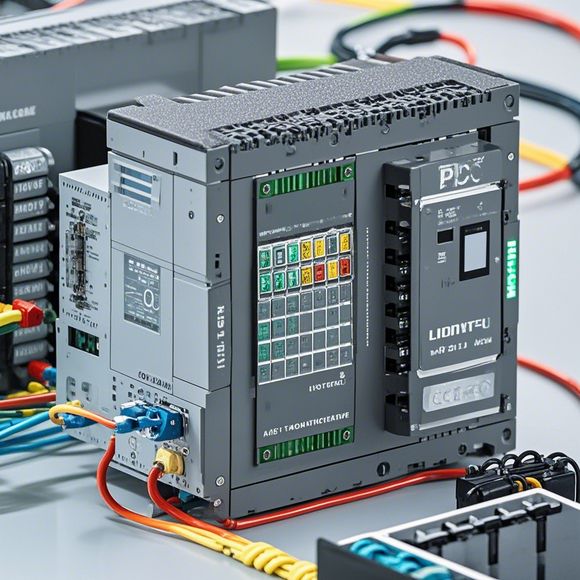
1、PLC: The brain of the system, the Programmable Logic Controller. It's responsible for processing commands and generating output signals based on predefined logic.
2、Input Devices: These are sensors or actuators that provide feedback to the PLC. They can be temperature sensors, pressure sensors, or motor controllers, among others.
3、Output Devices: These are devices that respond to the PLC's commands. They could be lights, valves, or motors, depending on the application.
4、Power Supply: A reliable power source is essential for maintaining the stability of the system. It ensures that the PLC and other components receive sufficient voltage and current.
5、Electrical Connectors: These are the physical connections that link the PLC to its peripheral devices. They must be securely fastened to prevent short circuits or damage.
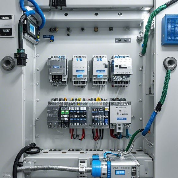
6、Circuit Breakers: These protect the system against potential electrical hazards by tripping the circuit if too much current is drawn.
7、Wires and Cables: These carry the electrical signals from one device to another. They must be of high quality and designed to handle the expected load.
8、Switches and Relays: These devices control the flow of electricity, enabling or disabling certain components based on predefined conditions.

9、Filters and Grounding: To prevent interference and ensure safety, filters and grounding systems are essential.
Now, let's dive deeper into the importance of each component and how they work together:
PLC: The heart of the system, responsible for processing commands and generating output signals based on predefined logic. It's the brain of the system, making decisions based on data input from various sources.
Input Devices: These are sensors or actuators that provide feedback to the PLC. They can be temperature sensors, pressure sensors, or motor controllers, among others. Their role is to detect changes in the environment and trigger corresponding actions within the system.
Output Devices: These are devices that respond to the PLC's commands. They could be lights, valves, or motors, depending on the application. Their function is to execute the instructions provided by the PLC and transform them into observable results.
Power Supply: A reliable power source is essential for maintaining the stability of the system. It ensures that the PLC and other components receive sufficient voltage and current. Without proper power supply, everything else falls apart.
Electrical Connectors: These are the physical connections that link the PLC to its peripheral devices. They must be securely fastened to prevent short circuits or damage. They serve as the bridge between the PLC and the world around it, connecting everything together.
Circuit Breakers: These protect the system against potential electrical hazards by tripping the circuit if too much current is drawn. They're like lifeguards at the beach, keeping everyone safe from danger.

Wires and Cables: These carry the electrical signals from one device to another. They must be of high quality and designed to handle the expected load. They're like messengers carrying important messages from point A to point B without getting lost.
Switches and Relays: These devices control the flow of electricity, enabling or disabling certain components based on predefined conditions. They're like traffic lights, signaling when to go and when to stop.
Filters and Grounding: To prevent interference and ensure safety, filters and grounding systems are essential. They help eliminate noise and maintain a stable electrical environment.
In conclusion, understanding the I/O wiring diagram is crucial for any foreign trade operation looking to optimize their production line. By following the steps outlined above, you can gain a comprehensive understanding of how to connect and manage the various components of your PLC system. Remember, a well-maintained and properly wired system will not only enhance productivity but also reduce downtime and increase overall efficiency. So, don't hesitate to invest in professional training and guidance when it comes to PLC wiring. With the right knowledge and tools, you can confidently navigate the complexities of your industrial control system and achieve unparalleled success in your foreign trade operations.
Content expansion reading:
Articles related to the knowledge points of this article:
PLC Controller for Manufacturing Automation
PLC Programming for Automation Control in the Manufacturing Industry
PLC (Programmable Logic Controller) Control System Basics
Plumbers Rule! The Role of PLC Controllers in the World of Waterworks
The Role of Programmable Logic Controllers (PLCs) in Foreign Trade Operations