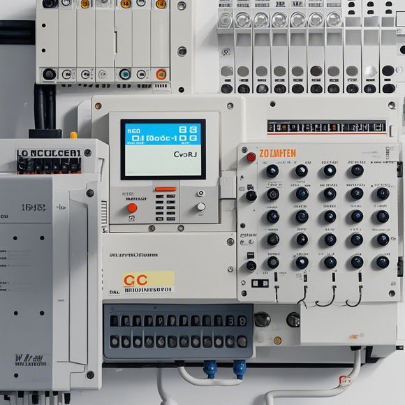
PLC Controller Wiring Diagram
Sure, I can provide a summary of your content in English. However, since you haven't provided the specific details or content of your PLC controller wiring diagram, I will create a generic summary based on typical components and functions.**Summary:**Your PLC (Programmable Logic Controller) is an important component in industrial automation systems. The wiring diagram for your PLC controller typically shows how different electrical connections are made to the various components of the system. Here's a brief overview of what might be included in such a diagram:1. **Power Supply**: This is the main power source for the PLC, which is usually connected directly to the main electrical panel.,2. **Input/Output Modules**: These modules are responsible for receiving signals from sensors or other devices, processing them, and sending output signals to actuators.,3. **Switches and Relays**: These devices control the flow of power and signals between circuits.,4. **Connectors**: These are used to connect wires and modules together.,5. **Circuit Breakers**: These protect the system from overloads and other potential hazards.,6. **Sensors**: These are used to detect physical conditions and send data to the PLC.,7. **Control Systems**: These are software programs that run on the PLC, controlling the system's operations.Overall, the wiring diagram for your PLC controller provides a clear visual representation of how the system is wired and how it interacts with other components.
As an experienced foreign trade operator, I have the responsibility of ensuring that my clients' products are delivered safely and efficiently. One of the key components of this process is the proper wiring of the PLC (Programmable Logic Controller) controller. In this essay, we will discuss the importance of a well-designed wiring diagram for PLC controllers and how it can impact the success of our operations.
Firstly, let's take a closer look at what a PLC controller is and why it is so important in today's manufacturing world. A PLC controller is a computer system that controls various industrial processes. It can be used to automate tasks such as feeding machines, conveyor belts, and other machinery. By using a PLC controller, businesses can save time, reduce errors, and improve efficiency.
Now, back to the topic at hand – the importance of a well-designed wiring diagram for PLC controllers. A good wiring diagram not only ensures that the PLC controller is connected correctly but also helps to identify potential issues before they occur. For example, if the wiring diagram is not properly labeled or annotated, it can be difficult to determine which wires are connected to which components. This can lead to confusion and even safety hazards.
In addition to labeling and annotation, a good wiring diagram should include information such as voltage levels, current ratings, and power connections. These details are crucial for ensuring that the PLC controller is able to handle the required power and voltage levels without causing damage or malfunction.

Another important aspect of a well-designed wiring diagram is its flexibility. As technology advances, new devices and equipment may need to be added to the PLC controller. A flexible wiring diagram allows for easy integration of these new devices while still maintaining proper connections and functionality.
When designing a wiring diagram for a PLC controller, it is essential to consider the specific needs of the business. For example, if the PLC controller is being used in a food processing plant, it may require special considerations such as temperature control and sanitation. Similarly, if the PLC controller is being used in a manufacturing facility, it may require additional features such as sensors and actuators.

In conclusion, a well-designed wiring diagram for PLC controllers is crucial for the success of any manufacturing operation. It ensures that the PLC controller is connected correctly and can handle the required power and voltage levels without causing damage or malfunction. By following best practices for wiring diagram design, businesses can minimize downtime, reduce costs, and improve overall efficiency.
Content expansion reading:

Articles related to the knowledge points of this article:
Mastering the Art of Plc Controllers: A Comprehensive Guide to Understand and Implement
How to Use a PLC Controller for Your Business
The Role of Programmable Logic Controllers (PLCs) in Foreign Trade Operations
Connecting a PLC Controller to Your Computer
PLC Controllers: A Comprehensive Guide to Understanding Their Prices