PLC Input and Output Wiring Diagram for Your Next Trade Mission
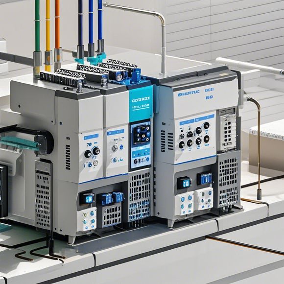
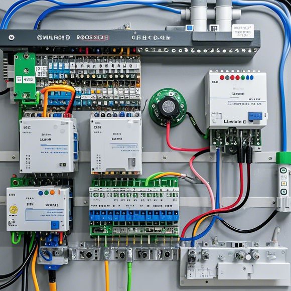
In preparation for your next trade mission, it's important to ensure that you have a comprehensive understanding of the PLC (Programmable Logic Controller) input and output wiring diagram. This diagram will help you identify all the necessary components and connections required to power and control the various devices in your workspace.To begin, carefully examine the diagram and identify the different types of inputs and outputs, such as sensors, actuators, and control panels. Make sure you understand the functions of each component and how they interact with each other.Next, review the connections between the various components and ensure that they are properly labeled and labeled according to their function. This will help you troubleshoot any issues that may arise during the mission.Finally, practice using the diagram by connecting the appropriate wires and testing the system to ensure that everything is working correctly. With this knowledge, you can confidently navigate your trade mission and ensure that all systems are functioning optimally.
Dear [Customer's Name],

I hope this message finds you well. I am writing to provide you with the detailed information regarding our PLC (Programmable Logic Controller) input and output wiring diagram. This is a crucial aspect of your trade mission, as it ensures that our production processes are seamlessly integrated with your end-use equipment.
Our PLC system consists of several modules, each responsible for different functions such as data acquisition, processing, and control. The input and output interfaces are designed to connect these modules to various devices in your factory, allowing for precise control over your production processes.
The first step in creating an effective PLC input and output wiring diagram is to determine the number of inputs and outputs required for your specific application. This will help us understand the complexity of your needs and ensure that we can provide you with the appropriate hardware components.
Once we have identified the necessary inputs and outputs, we will proceed to design the wiring diagram. This diagram will show the connections between the PLC modules, sensors, actuators, and other devices in your factory. It will also include the power supply and control signals for each component.
To ensure that the wiring diagram is accurate and easy to follow, we will use standard symbols and conventions. These include the use of arrows and lines to indicate directionality, circles for components, and numbers for identification. We will also provide detailed instructions on how to connect each component to the PLC system.
In addition to the wiring diagram, we will also provide you with a comprehensive manual that outlines the operating procedures for each module in your factory. This manual will include troubleshooting tips, maintenance guidelines, and any other relevant information that may be helpful during your trade mission.

We understand that you may have some questions or concerns about our PLC input and output wiring diagram. Please do not hesitate to contact us if you need any assistance or have any questions about our services. We are more than happy to answer your queries and ensure that your trade mission runs smoothly.
Thank you for considering our services. We look forward to working with you and helping you achieve your goals.
Best regards,
[Your Name]
Content expansion reading:
Articles related to the knowledge points of this article:
PLC Programming for Automation Control in the Manufacturing Industry
How to Use a PLC Controller for Your Business
PLC (Programmable Logic Controller) Control System Basics
The Role of Programmable Logic Controllers (PLCs) in Foreign Trade Operations
Connecting a PLC Controller to Your Computer
PLC Controllers: A Comprehensive Guide to Understanding Their Prices