PLC Controller Wiring Guide for Beginners
This PLC (Programmable Logic Controller) Wiring Guide is designed for beginners to help them understand how to wire up their PLC controller. It covers the basic principles of wiring, such as connecting the power and communication lines, and also provides detailed instructions on how to connect different components to the PLC. Additionally, it includes tips on troubleshooting common issues that may arise during the wiring process. With this guide, beginners can quickly learn how to properly wire up their PLC controller and ensure that it functions correctly.
Hello everyone, today I'm going to share with you a comprehensive guide on how to wire up your PLC controller. As a beginner in the field of automation, it's important to understand the basics of wiring so that you can effectively control and monitor your industrial processes. So let's dive into the details.
Firstly, before we start, it's essential to have a clear understanding of what a PLC (Programmable Logic Controller) is. A PLC is a powerful tool used in industrial settings to automate various tasks such as controlling machines, monitoring systems, and managing data. It's a versatile device that allows you to program specific instructions based on inputs from sensors or other devices.
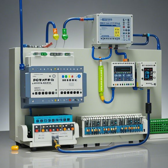
Now, let's get started with the wiring process. The first step is to identify the components needed for your PLC controller. This includes the PLC itself, power supply, sensors, actuators, and any other necessary hardware. Once you have all these components, you can begin connecting them together.
Here are the steps to follow:

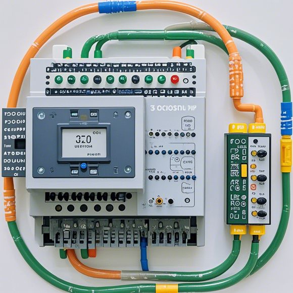
1、Connect the Power Supply: The first thing you need to do is connect the power supply to the PLC. Ensure that the correct voltage and current rating is selected for your PLC according to its specifications. You can use a power strip to manage multiple connections efficiently.
2、Connect the Sensors: Next, connect the sensors to the PLC. Depending on the type of sensor you have, you may need to adjust the input pins accordingly. For example, if you have a temperature sensor, you would connect one of the analog input pins to it. If you have a pressure sensor, you would connect another analog input pin to it.
3、Connect Actuators: Now, connect the actuators to the PLC. Again, depending on the type of actuator you have, you may need to adjust the output pins accordingly. For example, if you have a motor, you would connect one of the digital output pins to it. If you have a valve, you would connect another digital output pin to it.

4、Test the Connections: Once you have connected all the components, it's time to test the connections. Make sure that each connection is secure and that there are no loose cables or exposed wires. Use a multimeter to check for continuity between different components to ensure that everything is working correctly.
5、Program the PLC: Finally, you need to program the PLC to control the various functions of your system. This involves writing code that will enable the PLC to interpret the inputs from the sensors and actuators and execute the corresponding commands. You can use a programming language like Arduino or LabVIEW to program your PLC.
In conclusion, wiring up your PLC controller can seem daunting at first, but with the right knowledge and tools, anyone can become proficient in this area. By following the steps outlined above, you can successfully connect your PLC components and program it to control your industrial processes efficiently. Remember to always consult the manufacturer's manual for specific guidance on your particular PLC model.

Content expansion reading:
Articles related to the knowledge points of this article:
PLC Programming for Automation Control in the Manufacturing Industry
How to Use a PLC Controller for Your Business
PLC (Programmable Logic Controller) Control System Basics
Connecting a PLC Controller to Your Computer
PLC Controllers: A Comprehensive Guide to Understanding Their Prices