PLC Control Cabinet Wiring Diagram Interpretation
Sure, I can help you with that. Here's a summary in English:"PLC (Programmable Logic Controller) Control Cabinet Wiring Diagram Interpretation"This topic involves understanding and interpreting the wiring diagram of a PLC control cabinet. A PLC is a device used for controlling industrial processes, and its control cabinet typically includes various components like sensors, actuators, and other devices. The wiring diagram represents the connections between these components and the PLC.To interpret this diagram, one needs to understand the components and their functions. For example, the sensors might measure physical parameters like temperature or pressure, while the actuators might be used to manipulate objects or systems. The wiring diagram shows how these components are connected to the PLC, and what signals are sent and received between them.Interpreting the wiring diagram is important because it helps in troubleshooting and troubleshooting issues in the system. If there are any errors or anomalies in the wiring, it will be easier to identify and fix them. Additionally, it can help in planning and designing the system, as well as in training new employees on how to operate the system.
As a foreign trade operations professional, when it comes to interpreting the PLC (Programmable Logic Controller) control cabinet wiring diagram, it's important to approach the task with an understanding of the basic principles and terminology used in electrical engineering. The PLC is a crucial component that controls various industrial processes by executing instructions written in a programming language. When dealing with a PLC control cabinet, understanding its wiring diagram is essential for ensuring safe and efficient operation.
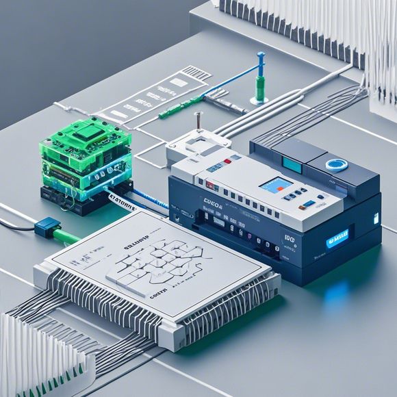
To begin with, let's take a look at the components of a typical PLC control cabinet. These include the CPU (Central Processing Unit), input/output modules, power supply, and interfaces like Ethernet or PROFIBUS. Each component plays a specific role in the overall system, and their connections are critical for maintaining the integrity of the circuitry.
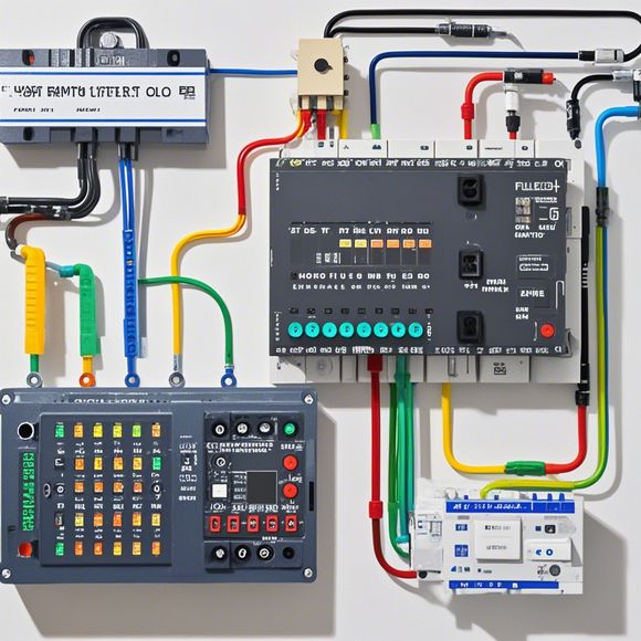
Now, let's focus on the wiring diagram itself. It typically consists of several lines, each representing a different type of connection. For example, the horizontal lines represent the physical connections between the various components, while the vertical lines indicate the electrical connections between the components. The labels on these lines provide detailed information about the connections, including the type of wire (e.g., AC or DC), the voltage level, and the function of the connection (e.g., power supply, signal transmission).
When interpreting the wiring diagram, it's important to pay attention to the following points:

1、Identify the PLC Model: The first step is to determine the model of the PLC being used in the system. This will help you understand the specific requirements for connecting the PLC to the other components.
2、Understand the Power Supply: The power supply is responsible for providing the necessary voltage and current to the PLC. It's essential to ensure that the correct voltage levels are being applied to the PLC, and that the power supply is capable of handling the load.
3、Connect the Input/Output Modules: The input/output modules are responsible for receiving and transmitting signals from external devices. When interpreting the diagram, pay attention to the types of connections required for each module, such as digital or analog connections.

4、Establish Connections Between Components: Once you have identified the connections required for each component, it's time to establish them. This may involve physically connecting wires together, or configuring software settings within the PLC to control the connections.
5、Test the System: After completing the wiring, it's important to test the system to ensure that everything is working correctly. This may involve running tests to verify that the PLC is receiving and processing signals properly, or checking that the power supply is providing adequate voltage and current.
6、Document the Work: Finally, it's important to document the work done during the wiring process. This includes recording the connections made, any modifications made to the diagram, and any issues encountered during the testing phase.

In conclusion, interpreting a PLC control cabinet wiring diagram requires a thorough understanding of electrical engineering principles and a keen eye for detail. By following these steps and paying close attention to the details on the diagram, you can ensure that your PLC control cabinet is safely and efficiently connected to the rest of the system.
Content expansion reading:
Articles related to the knowledge points of this article:
Mastering the Art of Plc Controllers: A Comprehensive Guide to Understand and Implement
PLC Programming for Automation Control in the Manufacturing Industry
How to Use a PLC Controller for Your Business
Plumbers Rule! The Role of PLC Controllers in the World of Waterworks
The Role of Programmable Logic Controllers (PLCs) in Foreign Trade Operations