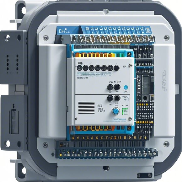
PLC Connection Diagram and Schematic Analysis
As a foreign trade operator, I'm tasked with ensuring that our products meet the standards of international markets. One critical aspect of this process is accurately understanding the connections and wiring diagrams for our PLC (Programmable Logic Controller) systems. This involves not only analyzing the physical layout of the hardware but also interpreting the electrical schematics to ensure that our systems are functioning correctly and efficiently.
To begin with, the first step in any PLC connection analysis is to thoroughly examine the physical connection diagram. This typically includes identifying each component, including sensors, actuators, and other devices connected to the PLC. It's important to note that the physical layout can vary significantly depending on the application, so it's crucial to have a clear understanding of how the components are arranged.
Once we have a good grasp of the physical layout, we move on to the electrical schematics. These diagrams detail the connections between various components, including wires, terminal blocks, and power sources. By examining these diagrams, we can determine which wires are used for input and output signals, as well as identify the voltage levels and current requirements for different components.
One common challenge in PLC connection analysis is dealing with complex wiring diagrams that may include multiple layers of interconnectivity. In such cases, it's essential to carefully review each section of the diagram to ensure that all connections are properly labeled and accounted for. Additionally, it's important to consider the potential impact of changes to the wiring diagram on the overall functionality of the system.

Another important consideration when analyzing PLC connections is the need for safety measures. For example, some applications require additional safety features such as overcurrent protection or grounding circuits. By carefully reviewing the electrical schematics, we can ensure that these safety measures are implemented correctly and effectively.
In addition to the technical aspects of PLC connections, it's also important to consider the practical implications of these connections. For instance, if there are any issues with the wiring diagram or the actual hardware, it could result in performance problems or even safety hazards. Therefore, it's essential to have a thorough understanding of the connections and their implications before proceeding with any further work.
Overall, PLC connection analysis is a critical step in ensuring that our products meet the needs of international markets. By carefully examining both the physical layout and electrical schematics, we can identify any potential issues and make necessary adjustments to improve the overall performance and reliability of our systems. As a foreign trade operator, it's important to stay up-to-date with the latest developments in PLC technology and best practices for connecting and integrating these systems into various applications.

Content expansion reading:
Articles related to the knowledge points of this article:
Smart Manufacturing Solutions with PLC Integrated Machinery
PLC Controller Wiring Guideline
PLC Controller for Manufacturing Automation
The Role of Programmable Logic Controllers (PLCs) in Foreign Trade Operations