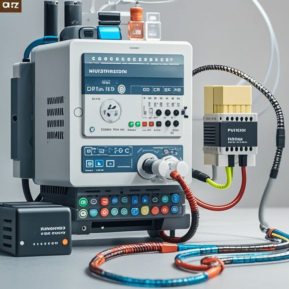
plc控制器接线图
Sure, I can help you with that! Here's a summary in English based on the content you provided:PLC (Programmable Logic Controller) is a type of industrial automation controller that allows for the creation and execution of control programs. When it comes to connecting PLCs, there are several key components involved, including input/output modules, power supplies, and communication interfaces.Input/Output modules are responsible for receiving and transmitting signals from sensors or other devices, while power supplies provide the necessary electrical energy for the PLC to operate. Additionally, communication interfaces such as Ethernet or PROFINET allow for the connection of PLCs to the internet or other networks for remote monitoring and control.Overall, understanding how to connect PLCs involves carefully planning the wiring diagram, selecting appropriate hardware components, and following the manufacturer's instructions for installation and programming.
"Mastering the Art of PLC Controller Wiring: A Step-by-Step Guide for Successful Automation Projects"
Hey there! I'm excited to dive into the world of PLC controller wiring, and let me tell you, it's a whole new ballgame. So, without further ado, let's start off with some basics.
First things first, we need to have a clear understanding of what a PLC (Programmable Logic Controller) is. It's like your personal assistant on steroids – it's designed to handle all the complex tasks that come with automation. But before we can even think about programming our PLC, we need to know how to connect it to the wires.
Now, let's talk about the wiring diagram. This is like a roadmap that tells us exactly where each piece of hardware should go. It's not just about connecting wires together; it's about ensuring that everything works seamlessly together. And trust me, it's not as easy as it seems. There are so many different types of wires out there, and each one has its own set of rules.

For example, let's say we have a motor controller that needs to be connected to the PLC. The first step is to identify the type of wire that goes into the motor controller. Is it a power wire or a ground wire? Once we know that, we can start thinking about where to route the wires.
But wait, there's more! We also need to consider the voltage level of the wires. Different wires are rated for different voltage levels, and if we mix them up, we could end up with a fire hazard or other serious issues. So, it's important to pay attention to the labels on the wires and make sure they match up correctly.
Now that we've covered the basics, let's move on to some more advanced topics. For example, let's say we want to add some sensors to our system. How do we do that? Well, again, the wiring diagram is our best friend here. We need to find out where the sensors will be installed and then route the wires accordingly.
Of course, there's more to it than just connecting wires. We also need to make sure that the wiring is done safely and securely. This means using proper insulation, making sure that the connections are tight, and avoiding any potential trip hazards.

And don't forget about testing! After all the hard work is done, it's always a good idea to run some tests to make sure everything is working properly. This may involve checking the output from the PLC and seeing if it matches up with the expected results.
So there you have it – the basics of PLC controller wiring. Of course, there's a lot more to it than this, but hopefully this gives you a good starting point. Remember, practice makes perfect, so don't be afraid to get your hands dirty and try out different techniques. Good luck with your automation projects!
Content expansion reading:
Articles related to the knowledge points of this article:
PLC Controller Selection Guide for Foreign Trade Operations
PLC (Programmable Logic Controller) Control System Basics
Plumbers Rule! The Role of PLC Controllers in the World of Waterworks
Connecting a PLC Controller to Your Computer
PLC Controllers: A Comprehensive Guide to Understanding Their Prices