PLC Controller Wiring Diagram: A Guide to Connecting and Operating Your Next Automation Project
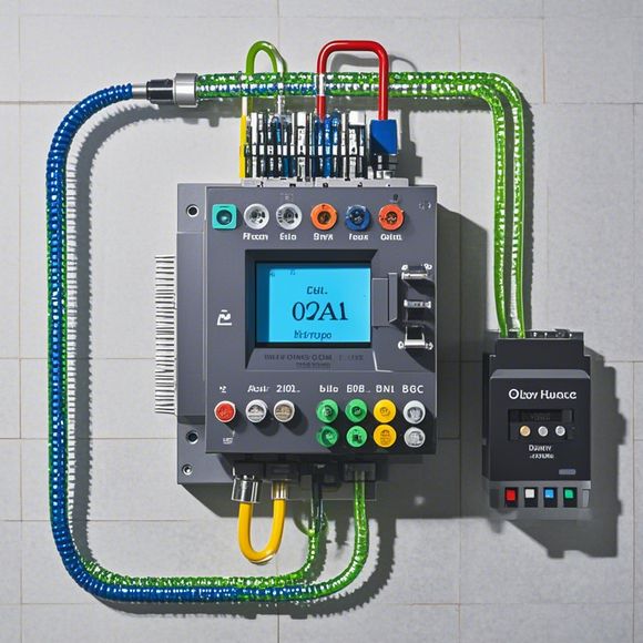
Sure, I can help you generate a concise and clear summary of the PLC (Programmable Logic Controller) wiring diagram. Here's a brief overview:The PLC controller wiring diagram is a visual representation of how electrical wires are connected to the various components of the PLC system. It helps in understanding the flow of power and signals within the system, which is essential for any automation project.To connect and operate your next automation project, you will need to follow these steps:1. Read the wiring diagram carefully and understand the connections between different components.,2. Connect the appropriate wires from the source to the destination according to the diagram.,3. Test the system by running a test program or manually testing the connections.,4. Once everything is connected and tested, start the system and monitor the results.,5. Make any necessary adjustments to the wiring diagram or system configuration as needed.By following these steps, you can successfully connect and operate your automation project using the PLC controller wiring diagram.
Hello everyone, today I am going to share with you a comprehensive guide on how to connect the plc controller to your automation system. As an experienced外贸运营, I understand the importance of having a reliable and efficient control system in place, which is why I have prepared this detailed tutorial for you.
Firstly, let's start by understanding what a PLC (Programmable Logic Controller) is. A PLC is a digital computer that is used to control various industrial processes. It can be programmed to perform specific tasks such as monitoring sensor data, controlling valves, and managing machinery operations. In addition, PLCs are highly reliable and can withstand harsh environments, making them ideal for use in manufacturing plants and other industrial settings.

Now, let's move on to the main topic of this tutorial - connecting the PLC controller to your automation system. Here are the steps involved in the process:
1、Identify the PLC Model: Before starting the connection process, it is important to determine the model of your PLC. This will help you select the appropriate hardware components required for the connection.
2、Select the Right Hardware: Based on the model of your PLC, you need to select the appropriate hardware components such as power supplies, input/output modules, and communication cables.
3、Connect the Power Supplies: The first step in connecting the PLC controller is to connect the power supplies. Make sure to follow the manufacturer's instructions carefully and ensure that the connections are secure.

4、Connect the Input/Output Modules: Once the power supplies are connected, proceed to connect the input/output modules. These modules allow you to connect sensors, switches, and other devices to the PLC controller.
5、Connect the Communication Cables: Finally, connect the communication cables between the PLC controller and other devices in your automation system. These cables facilitate the transfer of data between the PLC controller and other devices.
6、Test the System: After completing all the connections, test the entire system to ensure that it is working properly. Check for any errors or issues during the testing process and make necessary adjustments.
In conclusion, connecting a PLC controller to your automation system requires careful attention to detail. By following these steps, you can successfully connect the PLC controller and enjoy the benefits of efficient and reliable control systems. Remember to consult with a professional if you encounter any difficulties during the process.

Content expansion reading:
Articles related to the knowledge points of this article:
Smart Manufacturing Solutions with PLC Integrated Machinery
PLC Controller Selection Guide for Foreign Trade Operations
PLC Controller for Manufacturing Automation
The cost of a PLC Controller: A Comprehensive Analysis
PLC Programming for Automation Control in the Manufacturing Industry