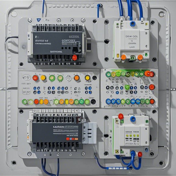
PLC Control Principle Diagram
PLC Control Principle DiagramIn the field of industrial automation, Programmable Logic Controllers (PLCs) play a crucial role in controlling and monitoring various industrial processes. The principle diagram for an PLC control system is a visual representation of the components and connections within the system. It helps engineers understand how the various inputs and outputs are interconnected to achieve specific control objectives.The principle diagram typically includes the following components:1. Central Processor Unit (CPU): The CPU acts as the brain of the PLC, processing input signals and generating output signals based on predefined logic.2. Input/Output Modules: These modules receive and process sensor data from various sources and send control signals to actuators.3. Interfacing Modules: These modules provide communication between the PLC and other devices or systems, such as computers or external hardware.4. Motor Drives: These modules convert electrical signals into mechanical motion, enabling the control of physical devices like motors and valves.5. Safety Modules: These modules ensure that the PLC system operates safely by providing fault detection and isolation mechanisms.Understanding the principle diagram of an PLC control system is essential for designing and implementing effective control strategies, troubleshooting issues, and maintaining the system's performance over time.
As a foreign trade operations manager, I'm responsible for ensuring that our products reach the right customers and meet their needs. To achieve this goal, we need to have a clear understanding of how our products are controlled using Programmable Logic Controllers (PLCs). In this article, I will explain the basic principles of PLC control and provide some practical tips on how to use them effectively.
Firstly, let's start with the concept of PLCs. They are digital computers that can be programmed to perform specific tasks based on instructions stored in memory. These instructions are called programs, which are written in a special language called ladder logic or structured text. Once the program is written, it can be uploaded into the PLC and executed automatically.
Now, let's talk about the main components of a PLC system. There are three main parts: the input device, the output device, and the central processing unit (CPU). The input device is responsible for receiving data from sensors or other devices, while the output device is used to send signals to actuators or other devices. The CPU is the brain of the PLC system, responsible for executing the program and performing calculations.
To create a PLC program, we first need to define the inputs and outputs that we want to control. This involves identifying the devices that need to be monitored and controlled, as well as the sensors or actuators that will be used to measure or manipulate the variables. Once we have identified the inputs and outputs, we can write the program in the special language used by PLCs.

One important aspect of PLC programming is the use of error handling. Since PLCs are digital devices, they can only process binary signals, which means that they cannot handle analog signals. This means that any errors or faults in the input signal must be detected and handled before the output signal is sent out. This is done through the use of error detection and correction circuits, which monitor the input signal and detect any errors before they affect the output signal.
Another important aspect of PLC programming is the use of safety features. Since PLCs are often used in dangerous environments, it is essential to incorporate safety features such as overload protection, short-circuit protection, and fire-extinguishing systems. These features help to ensure that the PLC system can operate safely even in the event of an emergency.
In addition to these technical aspects, it is also important to consider the user interface when designing a PLC system. A good user interface should be easy to use and intuitive, allowing operators to quickly understand how to control the system and troubleshoot any problems that may arise. This can be achieved through the use of visual displays, alarms, and other indicators that display important information about the system status.
Finally, it is important to consider the cost of implementing a PLC system. While PLCs can be expensive upfront, they can save money in the long run by reducing downtime, maintenance costs, and energy consumption. Additionally, PLCs can improve productivity by allowing for more efficient automation of production processes.

In conclusion, PLC control is a powerful tool that can be used to automate many industrial processes. By understanding the basic principles of PLC control, including the components of a PLC system, the programming language used, and the importance of safety features, we can design effective PLC systems that meet the needs of our customers. As a foreign trade operations manager, it is essential to stay up-to-date with the latest developments in PLC technology and best practices for implementing PLC systems in our businesses.
Content expansion reading:
Articles related to the knowledge points of this article:
PLC Programming for Automation Control in the Manufacturing Industry
How to Use a PLC Controller for Your Business
PLC (Programmable Logic Controller) Control System Basics
The Role of Programmable Logic Controllers (PLCs) in Foreign Trade Operations