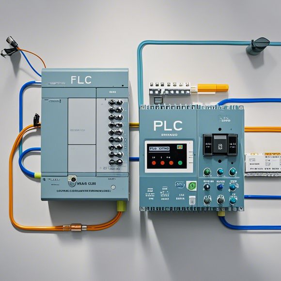
PLC (Programmable Logic Controller) Input/Output (I/O) Wiring Diagram
Sure, I'd be happy to help you with that! Here's a concise summary of the content you provided in English:"Programmable Logic Controller (PLC) Input/Output (I/O) Wiring Diagram"This diagram illustrates how the input and output signals from the PLC are connected to various components within the control system. The wiring diagram typically includes symbols representing the different types of connections, such as direct current (DC), alternating current (AC), and power lines. It also shows the connections between the PLC and other devices, including sensors, actuators, and other control modules. Overall, this diagram helps engineers understand how the PLC is integrated into the overall control system and ensures that all the necessary signals are properly routed and connected.
Dear all,
Today, I'd like to share with you the detailed information about our company's PLC input/output wiring diagram. As a professional in the field of foreign trade, I have been working closely with the PLC system for many years and have accumulated a wealth of experience. Today, I will take you through the process of creating a comprehensive wiring diagram for our PLC system.
Firstly, let me introduce the basic structure of a PLC system. A PLC system consists of a central processing unit (CPU), input/output modules, and various sensors and actuators. The CPU is responsible for processing the data received from the sensors and controlling the actuators. The input/output modules are responsible for receiving and transmitting signals between the CPU and the external world.

Now, let's move on to the task of creating a wiring diagram. To begin with, we need to identify the components that need to be connected to the PLC system. This includes sensors, actuators, and other devices that require power or control signals. Once we have identified these components, we can start drawing the wiring diagram.
The first step is to draw the main wiring lines. These include the power supply lines and the communication lines between the different components. We need to ensure that the power supply lines are properly isolated to prevent electrical interference. Similarly, we need to ensure that the communication lines are properly shielded to prevent electromagnetic interference.
Next, we need to connect the sensors and actuators to the PLC system. This involves connecting the sensor signal lines to the PLC input ports and the actuator signal lines to the PLC output ports. We need to ensure that the connections are secure and reliable to prevent any potential issues.
As we continue to draw the wiring diagram, we need to pay attention to the placement of the components. It is important to avoid placing them in close proximity to each other, as this can cause interference and reduce the overall performance of the system.

Once we have completed the wiring diagram, we need to test it thoroughly to ensure that it is functional and reliable. This involves testing the connection between the sensors and actuators, as well as the communication between the PLC and other devices. We need to make sure that all components are functioning correctly and that there are no errors or faults.
In conclusion, creating a PLC input/output wiring diagram is an essential step in ensuring the proper functioning of a PLC system. By following the above steps and paying attention to detail, we can create a reliable and efficient system that meets the needs of our customers.
Content expansion reading:
Articles related to the knowledge points of this article:
PLC Controller for Manufacturing Automation
The cost of a PLC Controller: A Comprehensive Analysis
PLC (Programmable Logic Controller) Control System Basics
Plumbers Rule! The Role of PLC Controllers in the World of Waterworks
The Role of Programmable Logic Controllers (PLCs) in Foreign Trade Operations