Detailed Explanation of PLC Connector Junctions
Sure, I can help you with that. Here's a summary of the PLC (Programmable Logic Controller) connector junctions:PLC connectors are used to connect various components and devices to a PLC. They are designed to provide a secure and reliable connection between the PLC and other electronic devices. The main types of connectors used in PLCs include:1. Single-pole, double-throw (SPDT) switches: These connectors are used to control the flow of power to and from the PLC. They have two contacts, one for each pole of the switch, which can be closed or opened separately.2. Multiplexers: These connectors allow multiple inputs to be connected to a single output pin on the PLC. They are useful for controlling multiple devices at once.3. TTL/CMOS compatible input/output connectors: These connectors are commonly used in PLCs and other electronic devices. They are designed to work with TTL (Transistor-Transistor Logic) and CMOS (Complementary Metal-Oxide-Semiconductor) devices.4. Analog input/output connectors: These connectors are used to connect analog signals to the PLC. They can be used for measuring temperature, pressure, or other physical quantities.5. Ethernet/IP connectivity: These connectors allow the PLC to communicate with other devices over an internet connection. They are commonly used for remote monitoring and control of PLC systems.
In the world of industrial automation, the powerhouse of control is the Programmable Logic Controller (PLC). These marvelous machines are the backbone of modern manufacturing and have revolutionized the way industries operate. But with great power comes responsibility, and understanding the intricacies of their connections is crucial for maintaining their functionality. Let's delve into the fascinating world of PLC connectors and how they work together to bring order to a factory floor.
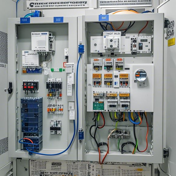
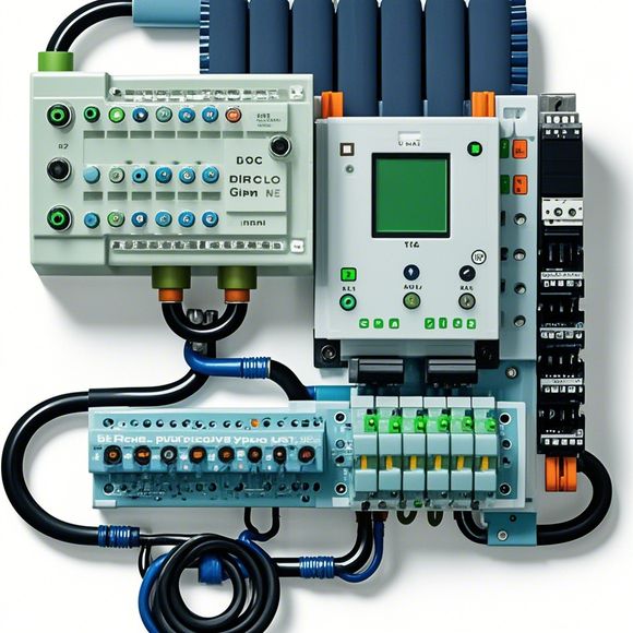
Firstly, it's important to understand that the PLC operates on a system of inputs and outputs, or I/O, which are connected through various types of connectors. The choice of connectors can vary depending on the application and the specific needs of the manufacturer. Some common connectors include screw terminals, bayonet terminals, and plug-in connectors. Each type has its advantages and disadvantages, and choosing the right one is essential for ensuring optimal performance.
Screw terminals are perhaps the most common connectors used in PLC systems. They are simple to install and disconnect, making them ideal for applications where frequent changes to the connections are necessary. However, they may not provide the same level of protection as other types of connectors, so care must be taken when selecting these.
Bayonet terminals, on the other hand, offer a more secure and reliable connection. They are designed to prevent accidental disconnection and are often used in applications where safety is paramount. However, they can be more difficult to install and require specialized tools.

Plug-in connectors are another popular option for PLC connections. They provide a high degree of flexibility and can accommodate a wide range of cable sizes. This makes them ideal for applications where custom configurations are necessary. However, they can also be more difficult to install and may require specialized equipment.
Now, let's talk about the importance of proper wiring practices. When connecting PLCs, it's crucial to follow industry standards and best practices. This includes using appropriate voltage and current ratings for the connections, using grounding techniques to ensure safe operation, and avoiding crosstalk or interference during communication.
Another important consideration is the selection of wires. Different materials have varying levels of resistance and insulation, which can affect the performance of the PLC. For example, copper wire is generally more resistant to electromagnetic interference than aluminum wire, but it can also conduct electricity better. Therefore, it's important to choose wires that match the requirements of the application and the environment in which the PLC will be installed.

One final point to consider is the placement of the connectors. Proper placement can help to reduce noise and improve signal quality. For example, placing the connectors away from sources of vibration or heat can help to minimize interference and ensure reliable communication.
In conclusion, understanding the intricacies of PLC connectors is essential for maintaining the functionality and reliability of these powerful machines. By following proper wiring practices and selecting the right connectors for your application, you can ensure that your PLC system operates at its best. So next time you're working with a PLC, take a moment to explore the different types of connectors available and how they can enhance your industrial control system.
Content expansion reading:

Articles related to the knowledge points of this article:
The cost of a PLC Controller: A Comprehensive Analysis
PLC Programming for Automation Control in the Manufacturing Industry
How to Use a PLC Controller for Your Business
Connecting a PLC Controller to Your Computer
PLC Controllers: A Comprehensive Guide to Understanding Their Prices