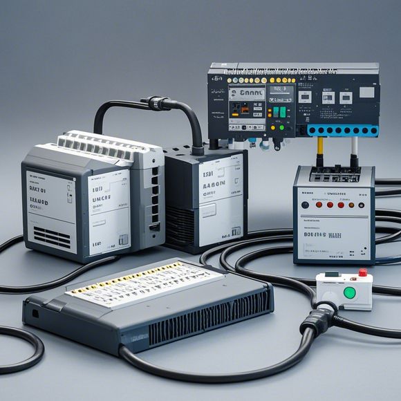
PLC Control System Principle Diagram
Sure, here's a simplified summary of the PLC (Programmable Logic Controller) Control System Principle Diagram:The PLC Control System is a digital control system that uses Programmable Logic Controllers to manage and control various industrial processes. The principle diagram of a PLC Control System typically includes several components such as sensors, actuators, input/output modules, and processors.Sensors are used to measure physical variables in real-time, while actuators are used to manipulate physical variables based on the measurements taken by the sensors. The input/output modules are responsible for transmitting data between the PLC and other devices in the process. The processor is the brain of the PLC, which interprets the data received from the sensors and controls the actuators accordingly.In summary, the PLC Control System is a digital control system that uses sensors, actuators, input/output modules, and processors to manage and control various industrial processes.
As a foreign trade operator, understanding the principles of PLC (Programmable Logic Controller) control systems is crucial for efficiently managing and operating industrial processes. The PLC system is a key component in modern automation technology, enabling precise control over various industrial processes. In this section, we will delve into the details of the PLC control system principle diagram, providing a comprehensive overview of its components and functions.
The PLC control system consists of several key components that work together to achieve complex automation tasks. These include the PLC itself, input/output modules, sensors, actuators, communication modules, and software. Each component plays a vital role in ensuring that the PLC can effectively monitor and control various industrial processes.

The PLC itself is the brain of the PLC control system, responsible for processing data from various sensors and actuators, as well as controlling the output devices based on pre-programmed logic. The PLC is designed to be highly reliable and durable, with features such as fault tolerance and redundancy to ensure continuous operation even in the event of hardware failure.
Input/Output modules are essential components that enable the PLC to interface with various external devices. They provide a connection point for sensors and actuators, allowing them to send data or trigger actions based on the input signals received from these devices. The Input/Output modules also facilitate communication between different PLCs or other devices within the same network.
Sensors are used to detect physical changes in the environment or internal conditions of an industrial process. For example, temperature sensors can detect temperature variations in a furnace, while pressure sensors can monitor pressure levels in a pipeline. These sensors generate analog or digital signals that are sent to the PLC, which then processes them to determine the appropriate action required to maintain optimal performance.
Actuators are devices that perform specific functions based on the commands generated by the PLC. For example, motors can be controlled by the PLC to rotate machinery or conveyors, while valves can be adjusted to regulate flow rates or pressures. The PLC communicates with these actuators through dedicated communication modules, allowing them to respond quickly and accurately to changing conditions in the industrial process.
Communication modules play a critical role in ensuring that the PLC can communicate effectively with other devices within the same network or across different networks. These modules enable data exchange between PLCs, sensors, and actuators, facilitating real-time monitoring, adjustment, and optimization of industrial processes. Some common communication protocols used in PLC systems include Profibus, Ethernet, and HART.

Software is the heart of the PLC control system, responsible for interpreting data and generating commands to control various processes. The software is typically written in a high-level language such as C or Assembly, which enables developers to create customized applications for specific industrial applications. The software also includes built-in algorithms and routines that can be used to automate complex processes and optimize performance.
In summary, the PLC control system is a powerful tool for managing and controlling industrial processes. By understanding the components and functions of the PLC control system, foreign trade operators can better design and implement efficient automation solutions for their operations. With proper planning and implementation, the PLC control system can significantly improve productivity, reduce energy consumption, and enhance overall operational efficiency.
Content expansion reading:
Articles related to the knowledge points of this article:
The cost of a PLC Controller: A Comprehensive Analysis
PLC Programming for Automation Control in the Manufacturing Industry
PLC (Programmable Logic Controller) Control System Basics
Plumbers Rule! The Role of PLC Controllers in the World of Waterworks
The Role of Programmable Logic Controllers (PLCs) in Foreign Trade Operations