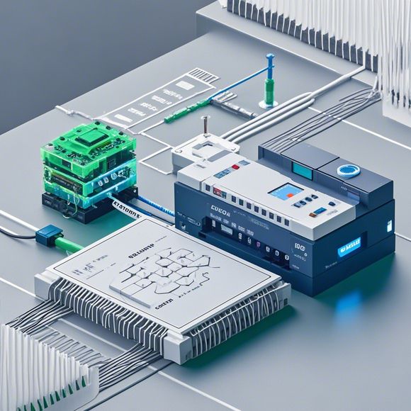
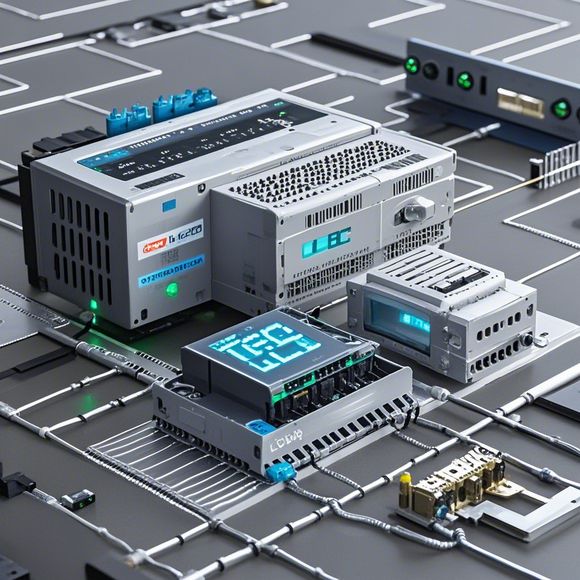
Introduction to PLC Controller Wiring Diagrams for Foreign Trade Operations
Sure, here is a summary in English based on the content you provided:Foreign trade operations require precise wiring diagrams for PLC controllers, ensuring that electrical connections are correctly made. These diagrams should include all necessary components and their respective connections, as well as any special requirements or safety precautions. It's important to follow the manufacturer's instructions and consult with an experienced electrician for accurate installation. With proper planning and attention to detail, foreign trade operations can be streamlined and successful.
Dear colleagues,
Welcome to this webinar on the subject of PLC controller wiring diagrams for foreign trade operations. Today, we will delve into the intricacies of these diagrams, providing you with a comprehensive understanding of how they can be used in various industries and their significance in enhancing efficiency and safety in our daily lives.
Firstly, let's define what a PLC (Programmable Logic Controller) is. A PLC is an electronic device that can be programmed to perform specific tasks based on pre-set instructions. It is commonly used in industrial settings, where it automates complex processes and controls equipment such as conveyors, pumps, and valves. In the context of foreign trade operations, a PLC can be used to manage inventory levels, monitor shipment statuses, and process customs documentation efficiently.
Now, let's talk about the importance of having a well-designed wiring diagram for your PLC controller. A wiring diagram serves as a visual representation of the connections between different components within the system. It helps you identify which wires are connected to which components, ensuring that everything is properly grounded and powered. Moreover, a well-written wiring diagram can help prevent errors during installation or maintenance, reducing downtime and minimizing potential hazards.

When creating a wiring diagram for your PLC controller, it's essential to follow certain guidelines. Firstly, ensure that all wires are labeled clearly, indicating their purpose and connection points. This helps in identifying the correct wires during troubleshooting and maintenance. Secondly, use appropriate voltage ratings for each wire, avoiding overloading or under-voltage conditions that could damage the PLC or other components. Thirdly, consider using color coding to differentiate between different types of wires, such as power, control, and signal wires. Finally, ensure that all connections are securely made using appropriate screws and connectors, and that there are no exposed wires or loose connections.
Now, let's move on to discussing some common components found in PLC controllers and their corresponding wiring diagrams. One of the most crucial components is the CPU (Central Processing Unit), which is responsible for processing instructions from the program code stored in memory. The wiring diagram for the CPU should show the connections between the CPU and other components such as input/output modules (I/O modules), communication modules, and memory modules. Additionally, it should also include information on the power supply and grounding connections required for the CPU.
Another important component is the I/O module, which interfaces with external devices such as sensors, actuators, and data acquisition systems. The wiring diagram for the I/O module should show the connections between the I/O module and other components such as motors, switches, and alarms. It should also include information on the power supply and grounding connections required for the I/O module.
The communication module is another critical component that enables the PLC to communicate with other devices or systems. The wiring diagram for the communication module should show the connections between the communication module and other components such as network cards, routers, and servers. It should also include information on the power supply and grounding connections required for the communication module.

Finally, the memory module is another important component that stores the program code for the PLC. The wiring diagram for the memory module should show the connections between the memory module and other components such as flash memory, RAM, and hard disk drives. It should also include information on the power supply and grounding connections required for the memory module.
In conclusion, a well-designed wiring diagram is essential for ensuring the proper functioning of a PLC controller in foreign trade operations. By following the guidelines outlined above and including relevant components and connections in your diagram, you can minimize errors and enhance efficiency while minimizing potential hazards. Remember to consult with experienced professionals when designing your wiring diagrams for optimal results.
Content expansion reading:
Articles related to the knowledge points of this article:
Mastering the Art of Plc Controllers: A Comprehensive Guide to Understand and Implement
PLC Controller Wiring Guideline
PLC (Programmable Logic Controller) Control System Basics
Plumbers Rule! The Role of PLC Controllers in the World of Waterworks
The Role of Programmable Logic Controllers (PLCs) in Foreign Trade Operations
PLC Controllers: A Comprehensive Guide to Understanding Their Prices