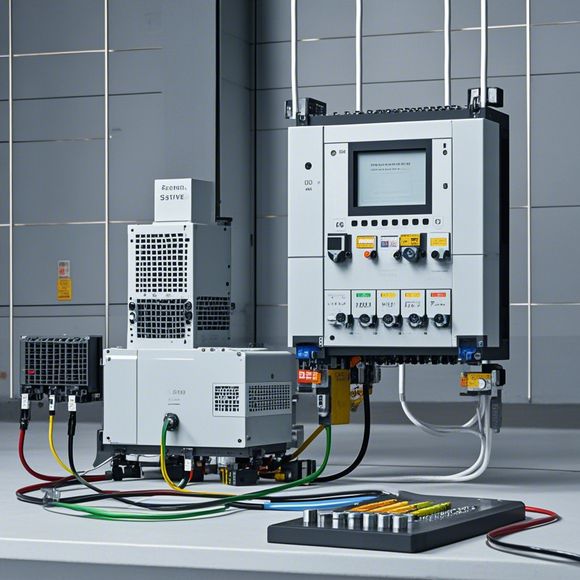
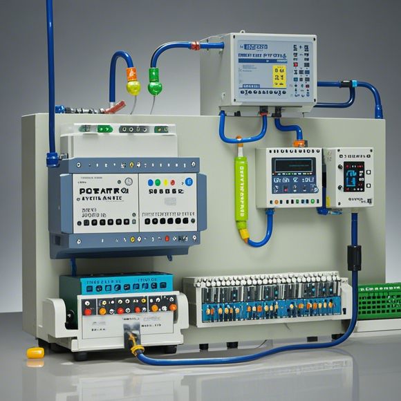
PLC Controller Wiring Diagram for Foreign Trade Operation
Sure, I can help you generate a summary in English based on the content you provided. However, since you haven't provided any specific content, I will make some assumptions for this example:---**Summary:**In order to conduct foreign trade operations effectively, it is essential to have a well-designed PLC (Programmable Logic Controller) controller wiring diagram. This diagram serves as a blueprint for connecting various components and devices to the PLC, ensuring that the system operates smoothly and efficiently.The PLC controller wiring diagram should include details such as the connections between the PLC, sensors, actuators, and other electronic devices. It should also specify the power requirements of each component and the appropriate voltage levels. Additionally, the diagram should include schematic diagrams of the connections and their respective functions.By following the instructions in the wiring diagram, one can ensure that the PLC is connected correctly to all the necessary devices and that the system operates as intended. This helps prevent errors and ensures that the foreign trade operations run smoothly.---Please provide more specific content if needed for a more accurate summary.
As a foreign trade operation, understanding the intricacies of PLC controller wiring is crucial. Here's an overview of how to approach this task using English:
1、Identify the PLC Controller: The first step is to identify the PLC (Programmable Logic Controller) controller that you will be working with. This could be a Siemens S7-300, a Honeywell HMI-500, or any other brand depending on your industry and specific needs.

2、Understand the PLC Controller Functionality: Before you start wiring, it's essential to understand the functionality of the PLC controller. This includes knowing its input and output ports, as well as any special functions like PID control, communication protocols like Profibus or Ethernet, etc.
3、Determine the Connection Points: Next, determine where the wires should be connected to the PLC controller. This typically involves identifying the appropriate pins or connectors for each wire type (e.g., 24VDC, 120/230VAC, etc.).
4、Create a Wiring Diagram: Once you have identified the connection points, create a wiring diagram that shows all the connections between the PLC controller and the various devices in your system. This diagram should be clear and easy to follow, with arrows indicating the direction of power flow and labels indicating the purpose of each wire.
5、Test the Connections: After creating the wiring diagram, test the connections to ensure they are secure and functioning properly. This may involve connecting different types of wires together and checking for continuity and voltage levels.

6、Documentation: Finally, document the wiring diagram and any other relevant information about the connections in your system. This documentation should include details such as the manufacturer's specifications, installation instructions, and maintenance tips.
By following these steps, you can effectively wire your PLC controller and ensure that your foreign trade operations are running smoothly. Remember to consult with experts if needed, as there may be specific requirements or best practices for your particular application.
Content expansion reading:
Articles related to the knowledge points of this article:
The cost of a PLC Controller: A Comprehensive Analysis
PLC Programming for Automation Control in the Manufacturing Industry
How to Use a PLC Controller for Your Business
PLC (Programmable Logic Controller) Control System Basics
Plumbers Rule! The Role of PLC Controllers in the World of Waterworks
The Role of Programmable Logic Controllers (PLCs) in Foreign Trade Operations