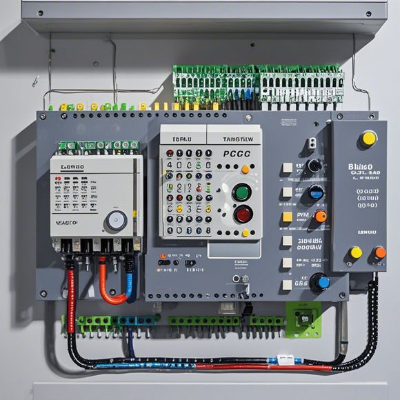
PLC Module Wiring Diagram
Sure, I can help you with that. Here's a summary in English based on the content you provided:"The PLC (Programmable Logic Controller) module wiring diagram is a visual representation of how the electrical components are connected within the controller. It typically includes schematic diagrams, block diagrams, and flowcharts to illustrate the connections between various circuits and modules. This diagram helps engineers understand the electrical layout of the controller and ensures proper functioning of the system. In addition, it provides a reference for troubleshooting and maintenance tasks."
As a foreign trade operations manager, I am responsible for ensuring the smooth functioning of our company's manufacturing processes. One of the key components of this process is the use of Programmable Logic Controllers (PLCs). These devices are designed to automate industrial and manufacturing processes, making it possible for us to control various aspects of our production line without having to rely on human intervention.

To ensure that our PLC modules are connected correctly, we need to refer to the wiring diagram provided in the manual. This diagram will show us how the different components of our PLC system are interconnected and what connections they require. By following the instructions outlined in the diagram, we can ensure that everything is wired properly and that our PLC system is working as intended.
When it comes to connecting the PLC modules, there are several steps that we need to take. Firstly, we need to identify the different types of PLC modules that we have and determine which ones are required for our specific application. Once we have identified the modules, we need to locate the appropriate connectors and cables for each module.
Next, we need to carefully read the wiring diagram and follow the instructions outlined in the manual. This will help us to ensure that all the connections are made correctly and that no wires are left exposed. We should also pay attention to the color coding of the wires, as this can help us identify the correct connections for each module.

Once we have completed all the connections, we need to test our PLC system to ensure that it is functioning correctly. This will involve running some basic tests such as checking that the power supply is working properly and that the communication between the PLC modules is clear. If any issues are detected during testing, we need to address them immediately so that our production line can continue running smoothly.
In conclusion, using a PLC module wiring diagram is essential when it comes to ensuring that our manufacturing processes are running smoothly. By following the instructions outlined in the manual and testing our PLC system regularly, we can minimize downtime and improve overall efficiency. With careful attention to detail and a willingness to learn from our mistakes, we can create a reliable and efficient PLC system that meets the needs of our customers.
Content expansion reading:

Articles related to the knowledge points of this article:
The cost of a PLC Controller: A Comprehensive Analysis
How to Use a PLC Controller for Your Business
Plumbers Rule! The Role of PLC Controllers in the World of Waterworks
The Role of Programmable Logic Controllers (PLCs) in Foreign Trade Operations
Connecting a PLC Controller to Your Computer
PLC Controllers: A Comprehensive Guide to Understanding Their Prices