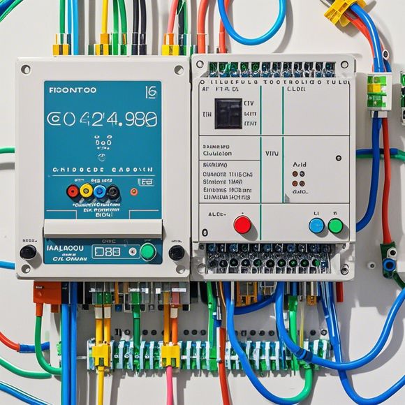
PLC (Programmable Logic Controller) Input and Output Wiring Diagrams
Sure, I'd be happy to help you with that! Could you please provide me with the content or topic you would like me to summarize in English?
Dear all,
As an experienced foreign trade operator, I am here to share with you the intricacies of PLC input and output wiring diagrams. These diagrams are crucial for ensuring that our manufacturing processes run smoothly and efficiently.

Firstly, let's start by understanding what a PLC is. A PLC is a computer system that controls industrial processes using programmable logic controllers. It can be used to monitor and control various aspects of a factory, such as temperature, pressure, and flow rate.
Now, let's talk about the importance of input and output wiring diagrams. These diagrams provide a visual representation of how the PLC communicates with other devices in the factory. They show the connections between the PLC, sensors, actuators, and other equipment. By examining these diagrams, we can identify any potential issues or areas for improvement in our production process.
For example, if we notice that the temperature sensor is not working correctly, we can quickly determine that there is a problem with the wiring or the sensor itself. This will allow us to take corrective action before the production line suffers any further damage.
Another important aspect of input and output wiring diagrams is their ability to provide data on the performance of the PLC. By analyzing the data collected from the sensors and actuators, we can gain valuable insights into how the factory is operating. This information can help us optimize our production processes and reduce waste.
In addition to providing technical data, input and output wiring diagrams also play a role in communication within the factory. They serve as a common language between different departments, allowing them to easily understand each other's needs and requirements.

Of course, as with any complex system, there may be some challenges when it comes to interpreting these diagrams. For example, different manufacturers may have slightly different terminology or conventions for describing their wiring diagrams. However, with practice and experience, we can become adept at deciphering these diagrams and making informed decisions based on the information they contain.
In conclusion, input and output wiring diagrams are essential tools for any foreign trade operator looking to ensure that their manufacturing processes run smoothly and efficiently. By understanding the importance of these diagrams and practicing good communication skills, we can minimize errors and maximize productivity. So let's embrace this knowledge and continue to improve our operations!
Content expansion reading:
Articles related to the knowledge points of this article:
PLC Controller Wiring Guideline
The cost of a PLC Controller: A Comprehensive Analysis
PLC (Programmable Logic Controller) Control System Basics
Connecting a PLC Controller to Your Computer
PLC Controllers: A Comprehensive Guide to Understanding Their Prices