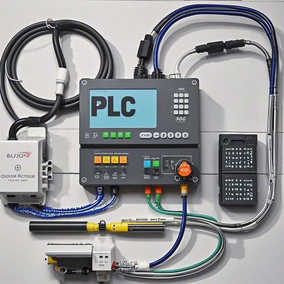
Understanding PLC Circuit Diagrams with a Glimpse Through the Picture
In this digital world, understanding PLC (Programmable Logic Controller) circuit diagrams has become increasingly crucial for various industrial applications. By taking a "glimpse through the picture" approach, we can gain a deeper understanding of these complex systems.Firstly, let's define what a PLC circuit diagram represents. It is a visual representation of how the electrical components are connected within an industrial process. These components include sensors, actuators, and processors, all working together to perform specific tasks such as controlling valves, monitoring temperature, or adjusting machinery speed.Now, let's talk about the importance of understanding these diagrams. They serve as a blueprint for optimizing production processes, reducing downtimes, and ensuring safety. For example, if a fault occurs in a particular circuit, it can be quickly identified by reviewing the diagram. This helps prevent larger problems from arising and ensures that the plant remains productive.Furthermore, PLC circuit diagrams can also be used for training new employees. By having a clear understanding of these diagrams, they can better grasp the principles behind the system and perform their duties effectively.In conclusion, understanding PLC circuit diagrams is essential for those working in industries that rely on automation. A "glimpse through the picture" approach can greatly enhance our ability to analyze and troubleshoot these systems, ultimately leading to more efficient and reliable operations.
In this digital age, where technology is at the forefront of every industry and business operation, understanding the intricacies behind complex systems such as PLC (Programmable Logic Controller) circuit diagrams becomes crucial. As an experienced外贸运营, your ability to interpret these diagrams can significantly impact how you manage your sales channels, optimize inventory management, and improve overall efficiency within your company's operations. In this guide, we will delve into the key aspects of PLC circuit diagrams, providing insights that will enable you to better understand and navigate these technical documents effectively.
Firstly, let us start by discussing what a PLC circuit diagram is and its role in industrial automation. A PLC circuit diagram is an essential document that visually represents the electrical connections between various components in a control system. It serves as a blueprint for programming the logic and flow of signals within a particular industrial process, allowing for precise and efficient control of machinery and equipment. By understanding how the circuit diagram works, you can better comprehend how each component contributes to the overall functionality of a system, which is vital when dealing with complex machinery or processes.
Now, let's dive into how to read and analyze PLC circuit diagrams effectively. To begin with, familiarizing yourself with the basic elements of an PLC circuit diagram is crucial. These include the power supply, input devices, output devices, and control logic. Power supply refers to the source of electricity used to power the system, while input devices are sensors or other devices that provide feedback on system conditions. Output devices are the actuators that respond to the signals from control logic. Finally, control logic comprises the software algorithms that determine the actions taken based on the inputs and outputs.
Once you have a basic understanding of these elements, it's time to focus on the symbols commonly used in PLC circuit diagrams. Common symbols include relay contacts, LEDs, buttons, switches, and other indicators. Each symbol has a specific meaning and should be accurately identified to ensure clarity and consistency in communication. For example, a relay may be represented by a circle with two lines intersecting at a right angle, indicating that it controls another device. Similarly, a button might be shown as a small square labeled with letters representing the function it activates.

Another important aspect of analyzing PLC circuit diagrams is understanding how different components interact with each other. This involves identifying the relationships between input devices, output devices, and control logic. For instance, if a temperature sensor detects an increase in temperature, it triggers an output device (such as a valve) that opens to release hot air to cool down the room. Conversely, if a pressure sensor indicates a decrease in pressure, it sends a signal to control logic, which then activates a safety feature to prevent potential damage.
Furthermore, it's essential to recognize the importance of proper documentation and labelling in PLC circuit diagrams. Proper documentation ensures that all relevant information is clearly presented, making it easy for others to understand and follow the instructions. Labelling is also critical as it helps to avoid confusion by clearly defining the purpose of every component and their relationship to each other.
Additionally, it's worth noting that PLC circuit diagrams can vary greatly depending on the specific application or industry they belong to. Therefore, it's essential to be familiar with the conventions used in your industry or sector to ensure accurate interpretation. For example, in some industries, a relay may be used instead of an LED for signaling purposes.

Finally, it's important to remember that mastering PLC circuit diagrams requires practice and dedication. As an experienced外贸运营, you should continuously seek out opportunities to learn and hone your skills by reviewing existing examples, attending training sessions, or even taking on challenging projects. By doing so, you can become an expert in interpreting and managing PLC circuit diagrams, ultimately improving your overall efficiency and productivity.
In conclusion, understanding PLC circuit diagrams is an important skill for any professional working in the field of automation and industrial control. By following the guidance provided above, you can effectively navigate through these complex documents and make informed decisions about how best to utilize their features in your business operations. Remember, as you gain more experience, you will become even more adept at decoding these intricate schematics, enabling you to unlock new possibilities for growth and success.
Content expansion reading:

Articles related to the knowledge points of this article:
PLC Programming for Automation Control in the Manufacturing Industry
How to Use a PLC Controller for Your Business
Plumbers Rule! The Role of PLC Controllers in the World of Waterworks
Connecting a PLC Controller to Your Computer
PLC Controllers: A Comprehensive Guide to Understanding Their Prices