PLC Controller Wiring Diagram
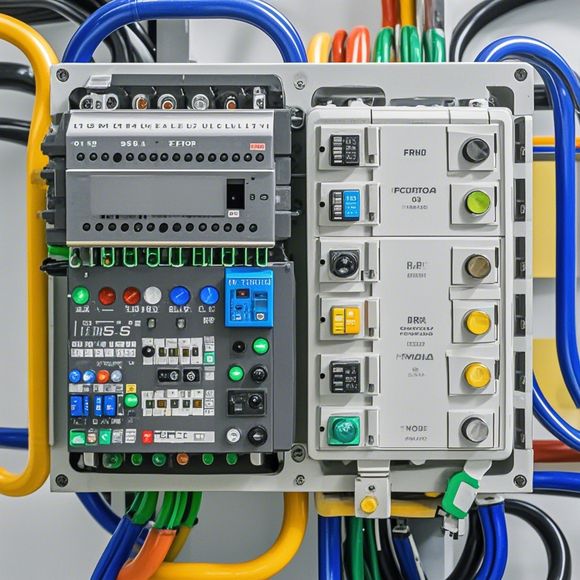
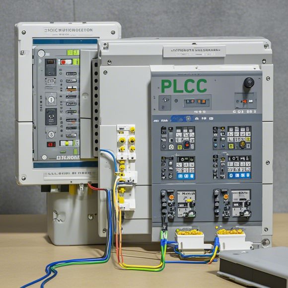
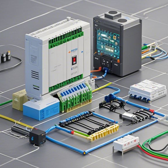
As a seasoned trader, I understand the importance of maintaining accurate and up-to-date knowledge about the intricacies of PLC controller wiring diagrams. These diagrams are critical in ensuring that our systems run smoothly and efficiently. They provide a visual representation of the connections between various components within the control system. By studying these diagrams, we can quickly identify any potential issues that may arise during the operation of the system and take corrective action accordingly.
When analyzing a plc controller wiring diagram, it's essential to first familiarize ourselves with the basic concepts and functions of different components. For example, we need to know how the PLC operates, what its input/output ports are, and how they are connected to other devices such as sensors and actuators. We should also understand the significance of each signal line and how they are used for communication between different components.
Once we have a good understanding of the basics, we can start examining the wiring diagram itself. This involves noting down all the components mentioned on the diagram along with their respective connections. Pay special attention to the power supply lines and grounding points, as these are crucial for preventing electrical shocks or other safety hazards. Additionally, look out for any labels indicating the polarity of the signals being transmitted between components.
It's important to note that not every wiring diagram will have all of these details. Some may only provide information on the connections between individual components, while others could be more detailed and include additional features like error codes or diagnostic information. In such cases, it's essential to consult the relevant documentation or contact the manufacturer for clarification.

Another important aspect of inspecting a plc controller wiring diagram is determining which wires should be connected to which terminals on the PLC. This process requires careful attention to detail and an understanding of the specific requirements of the system being designed or retrofitted. It's often necessary to refer to schematic diagrams or manuals that provide detailed information on how to properly connect various components together.
Once we have completed our analysis and identified all the necessary connections, it's time to test the system to ensure that everything works correctly. This involves running tests on various scenarios, such as changing input values, triggering alarms when necessary, and monitoring output signals for proper functioning. If anything seems off or there are any unexpected behaviors observed during testing, we need to investigate further and make any necessary adjustments to the wiring diagram.

Overall, inspecting a plc controller wiring diagram is a crucial step in ensuring the successful operation of any control system. With careful attention to detail, thorough research, and thorough testing, we can avoid common pitfalls and ensure that our systems run smoothly and safely for years to come.
Content expansion reading:

Articles related to the knowledge points of this article:
Smart Manufacturing Solutions with PLC Integrated Machinery
PLC Controller Selection Guide for Foreign Trade Operations
PLC Controller Wiring Guideline
The Role of Programmable Logic Controllers (PLCs) in Foreign Trade Operations
Connecting a PLC Controller to Your Computer
PLC Controllers: A Comprehensive Guide to Understanding Their Prices