PLC Controller Wiring Diagrams: A Comprehensive Guide for Understanding and Troubleshooting
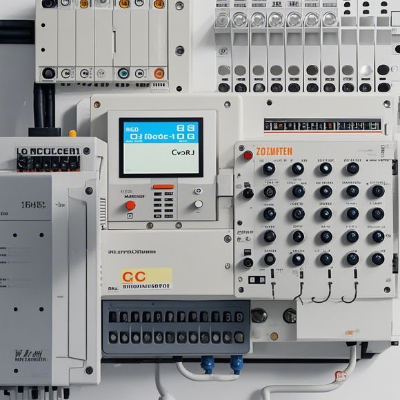
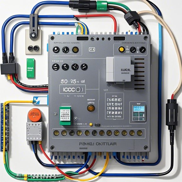
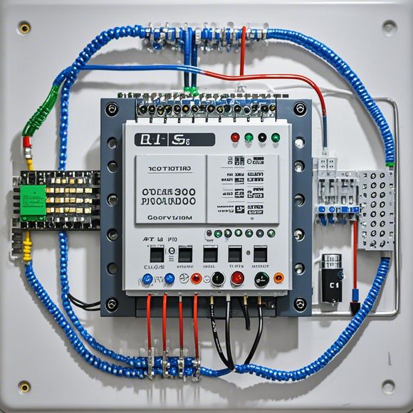
PLC (Programmable Logic Controller) is a crucial device in industrial automation systems. It's used to control and monitor processes, often replacing human intervention. To understand how it works, you need to understand its wiring diagrams.Wiring Diagrams are visual aids that show the connections between different components of the PLC, such as sensors, actuators, and other devices. They help you identify which components are connected where, and how they interact with each other.To read a wiring diagram, start by identifying the main components - these are usually the PLC, sensors, and actuators. Then, look at the connections between these components. Each connection should have a label indicating the type of connection, such as wire or relay. This will help you understand what each component does and how they work together.If you're having trouble troubleshooting issues, a wiring diagram can also be useful. You can use it to identify any problems that may be preventing your system from functioning correctly. For example, if you notice that one sensor is not working properly, you can refer to the diagram to see if it has an issue with its connection or if there's a problem with another component.
Dear fellow trade partners,

I hope this message finds you in good spirits. As your trusted partner in the realm of international trade, I am thrilled to share with you a comprehensive yet engaging guide that is sure to enlighten and assist you in your endeavors as an importer or exporter. Our focus today is on the intricate world of PLC controller wiring diagrams. These diagrams are the backbone of industrial automation, and their proper understanding can mean the difference between success and failure in a manufacturing process. So let's delve into this fascinating topic together!
Firstly, it is important to understand what a PLC (Programmable Logic Controller) is. In simple terms, a PLC is a device that is designed to execute complex instructions based on programming code. It serves as the brain of an industrial system, controlling various aspects such as temperature, pressure, and motion. The beauty of a PLC is that it can be programmed to perform a variety of functions, from simple logic gates to advanced algorithms.
Now, let's talk about the importance of wiring diagrams in the context of PLC controllers. A wiring diagram is a visual representation that outlines how the different components of a system communicate with each other. It is akin to a roadmap that shows the path of electrical power and signals through the system. Without a clear understanding of these diagrams, you risk causing confusion, errors, and even safety hazards.
So, how do we create a wiring diagram? Here are the steps:
Step 1: Gather all necessary information. This includes the physical layout of the factory floor, the specifications of the equipment being controlled, and the desired outputs from the system.

Step 2: Identify the primary components. These are the devices and circuits that are directly connected to the PLC controller. For example, the input devices (sensors), output devices (actuators), and communication lines (buses) are all primary components.
Step 3: Determine the connections required to connect these components. This involves identifying where the power supply, signal lines, and ground connections will go.
Step 4: Draw the wiring diagram. Using specialized software, such as AutoCAD, sketch out the connections between the components and the PLC controller. Ensure that all wires are routed correctly, following established standards for electrical safety and compatibility.
Step 5: Test the system. Once the wiring diagram has been completed, test the entire system to ensure that it operates correctly. This includes verifying that all sensors, actuators, and communication lines are functioning properly and that the output signals are reaching their intended destinations.
And there you have it! A brief overview of the key points to remember when creating and understanding PLC controller wiring diagrams. By following these steps, you can avoid common pitfalls and ensure that your industrial automation systems run smoothly. Remember, investing in a reliable wiring diagram saves time, money, and headaches down the line.

So, dear friends, let us embrace this knowledge and take our industrial automation journey to new heights! Together, we can achieve unparalleled precision, efficiency, and success in our global trade ventures. Thank you again for joining me on this enlightening journey!
Best regards,
[Your Name]
Content expansion reading:
Articles related to the knowledge points of this article:
Mastering the Art of Plc Controllers: A Comprehensive Guide to Understand and Implement
PLC Controller Wiring Guideline
Plumbers Rule! The Role of PLC Controllers in the World of Waterworks
Effective Strategies for Handling PLC Control System Faults
What is a Programmable Logic Controller (PLC)
PLC Controller Advantages: A Comprehensive Guide for Success in Global Trade