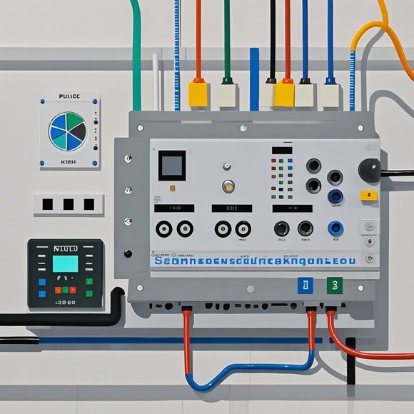
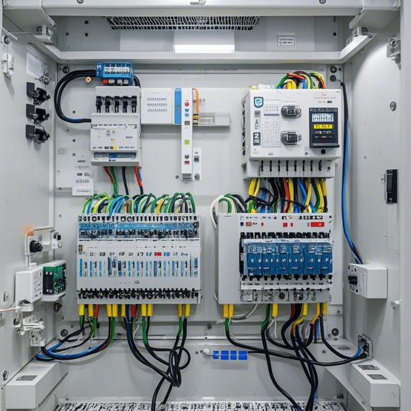
Understanding the PlC Circuit Diagram through an Image
As an AI model, I'm not able to directly interpret images. However, I can provide you with a summary or interpretation of the PlC Circuit Diagram based on your description:,The PlC circuit diagram is typically used in electronics and digital engineering. It represents a combinational logic circuit that uses flip-flops (FFs) as the basic building blocks. Flip-flops are memory elements that store data and can be toggled (set to 1 or 0). The PlC circuit diagram shows the connections between the inputs, outputs, and flip-flops in the circuit.,In this type of circuit, each flip-flop stores only one binary value at any given time. This is because flip-flops are designed to be simple and efficient for storing binary data. The circuit also includes multiplexers and decoders, which are used to select and route the signals between different components.,Overall, the PlC circuit diagram is important for designers who need to understand and implement digital systems that use combinational logic.
Opening Statement:
Hello, fellow traders and enthusiasts of electrical engineering. Today, we're going to delve into a complex yet fascinating topic - understanding the plc (programmable logic controller) circuit diagram. Let me start by sharing a story about how I stumbled upon this knowledge.

As an avid reader and enthusiast of technology, I have always been curious about how different components come together to create something that can be controlled with a simple click of a button. One day, I was tasked with working on a project that required me to program a plc to perform certain tasks. At first, everything seemed like a puzzle waiting to be solved. But as I delved deeper into the circuit diagram and began to understand each component's function, I realized that it wasn't just a puzzle but rather a beautiful tapestry woven together by countless wires and circuits.
Now, let's talk about the basics. A plc circuit diagram is a visual representation of the electrical connections between various components within a plc system. It serves as the blueprint for how the plc will operate, guiding us through the process of programming the system and troubleshooting any issues that may arise.
Firstly, let's talk about the inputs. The input section of a plc circuit diagram includes all the devices that receive data from other sources such as sensors, switches, or other devices. This section is critical in ensuring that the plc is receiving accurate information and can make informed decisions based on that data.
Next up is the output section. Here, we find the device(s) that send data out to the world around us, such as motors, lights, or other devices that we want to control. This section is where the magic happens; we program the plc to execute commands sent through the input section and transform those commands into actionable steps.
Now, onto the core components themselves. Let's begin with the central processing unit (CPU), which acts as the brain of the plc. It processes data from the input section and decides what actions to take based on that data. If you were to describe the CPU as a computer processor, you'd probably say that it's like a tiny supercomputer that sits quietly in the background, crunching numbers and making decisions.
But wait, there's more! The next stop is the memory unit, which stores the instructions that the CPU executes. This could be compared to a bank account where the instructions are stored until they're needed for execution. And finally, let's not forget about the input and output devices. These are the things that we use to interact with our plc, whether we're using buttons or levers or simply typing commands into a terminal screen.

Now, back to the story. As I delved deeper into the circuit diagram, I began to see patterns that made sense. For example, if I noticed that a particular relay was always activated during a specific sequence of operations, then I knew that I had to modify the code so that that relay would respond accordingly. Similarly, if I saw that a sensor was providing incorrect readings, then I knew that I had to check the wiring or adjust the parameters of the sensor itself.
Of course, there are many other components and subsystems involved in a plc system, but these are some of the key ones that I found most helpful when learning about them. By understanding the circuit diagram, we can gain a deeper appreciation for the intricate ways in which different components work together to create a cohesive whole.
In addition to being a useful tool for programming and troubleshooting, the plc circuit diagram also provides us with valuable insights into how different systems can be designed and optimized for efficiency and performance. For example, by analyzing the circuit diagram, we can determine which components need to be upgraded or replaced in order to improve the overall functionality of the system.
In conclusion, understanding a plc circuit diagram is not only a valuable skill for those who work with electronics but also a fascinating journey into the world of engineering and technology. It's like taking a walk through a labyrinthine forest, exploring every twist and turn until we arrive at the center of the puzzle. And once we do, we realize that there's no limit to what we can achieve with the power of knowledge and imagination.
Content expansion reading:
Articles related to the knowledge points of this article:
Smart Manufacturing Solutions with PLC Integrated Machinery
PLC Controller for Manufacturing Automation
The cost of a PLC Controller: A Comprehensive Analysis
PLC Programming for Automation Control in the Manufacturing Industry