PLC Control Cabinet Wiring Diagrams Comprehensive Guide
In this comprehensive guide, we'll delve into the intricate world of Programmable Logic Controller (PLC) cabling diagrams. These diagrams, like the intricate web of a bee's nest, represent the complex interplay between hardware components and software logic in industrial automation.From the humblest single-input single-output module to multi-functional systems with hundreds of inputs and outputs, every connection counts. A well-crafted schematic not only tells the tale of these connections but also guides us through the labyrinth of wire management, ensuring that each piece fits perfectly into its place.Whether you're a novice or a seasoned engineer, this guide will arm you with the knowledge to design and troubleshoot PLC control cabinet wiring diagrams with confidence. So let's embark on a journey of understanding and precision, unlocking the mysteries hidden within the wired tapestry of industrial automation.
As a foreign trade operation, understanding the intricacies of PLC (Programmable Logic Controller) control cabinet wiring is critical for ensuring reliable and efficient automation systems. This comprehensive guide aims to provide a detailed overview of the different components involved in constructing a PLC control cabinet, including sensors, actuators, switches, and other essential elements.

Firstly, it's essential to understand how the PLC controller communicates with various devices within the control cabinet. The PLC receives input signals from external sensors or switches, processes these data, and then sends output commands to corresponding actuators. In this guide, we will explore the various wires used for connecting the PLC to its various inputs and outputs.
One key component of any PLC installation is the power supply. The PLC requires a stable and reliable source of energy to function correctly. Therefore, it is crucial to ensure that the power supply is appropriately grounded and protected against potential hazards. Additionally, the use of appropriate voltage ratings ensures that the circuitry can handle the required power load without overheating or damage.
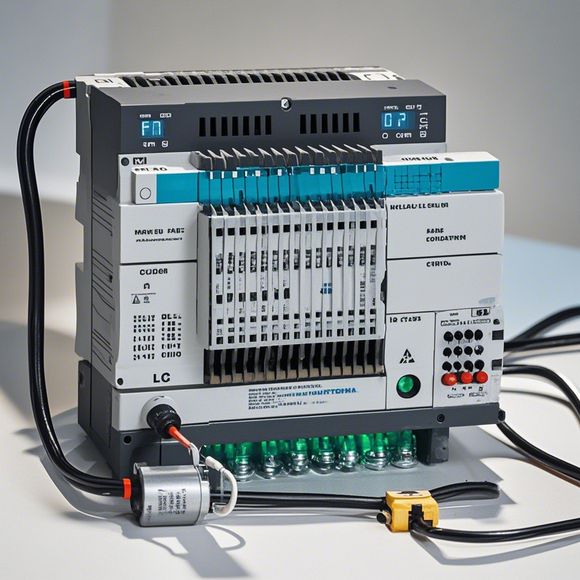
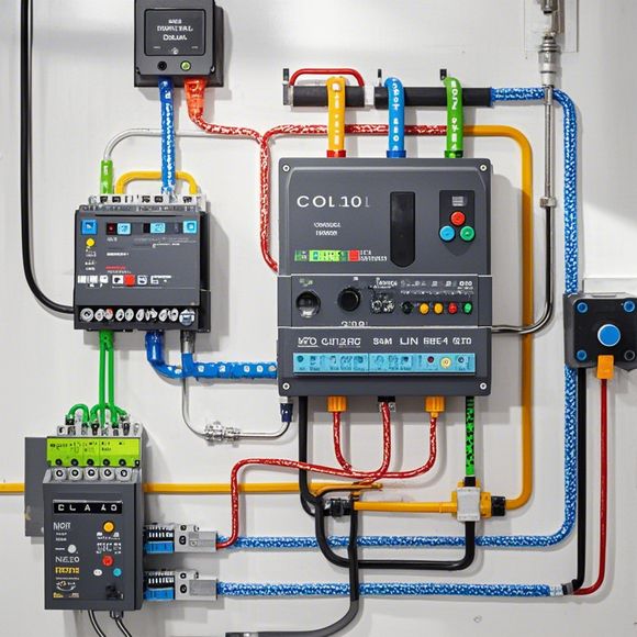
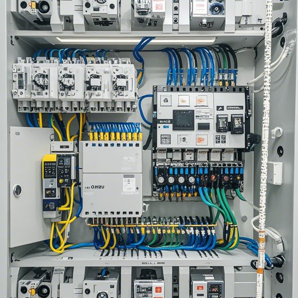
Next, we will delve into the wiring diagrams for each component of the control cabinet. These diagrams typically include schematic representations of the physical layout, showing the connections between different components such as sensors, actuators, and switches. Each component is connected to the PLC through specific wires, and these connections should be accurately labeled and marked according to industry standards.
For example, let's consider a typical sensor connection in the control cabinet. The sensor would be connected to an analog input port on the PLC, which converts the signal received into a digital value. This value is then processed by the PLC's software to determine whether the sensor reading is above or below a certain threshold. Based on this decision, the PLC sends appropriate control signals to either activate an actuator or trigger an alarm.

Another example involves an actuator, which may include motors or pneumatics. These devices are often controlled via solenoid valves or similar components, which are connected directly to the PLC's output ports. By programming the PLC to send specific signals to these valves, we can activate or deactivate them accordingly, enabling or disabling the corresponding device.
In addition to sensors and actuators, there are also various switches and relays that can be integrated into the control cabinet. For example, a contactor can be used to connect multiple circuits together, allowing for the distribution of power to various devices. Relays can also be employed to create circuit breakers or protect the system from overloads.
When wiring the control cabinet, it's important to ensure that all connections are secure and properly grounded to prevent electrical short circuits or shock hazards. Additionally, proper documentation should be created to track the location of all wires and connections, making maintenance and troubleshooting much easier in the future.
Finally, it's worth noting that PLC control cabinets can vary significantly in size and complexity depending on their intended purpose. Some may be designed for simple applications involving basic sensor-actuator pairs, while others may require advanced features such as real-time data monitoring, programmable logic, or remote access capabilities.

Overall, understanding the intricacies of PLC control cabinet wiring is crucial for ensuring optimal performance and reliability in any automation system. With this comprehensive guide in hand, you can confidently navigate the complex world of PLC control cabinet wiring and confidently implement the latest technology into your operations.
Content expansion reading:
Articles related to the knowledge points of this article:
Smart Manufacturing Solutions with PLC Integrated Machinery
Mastering the Art of Plc Controllers: A Comprehensive Guide to Understand and Implement
PLC Controller Wiring Guideline
PLC Programming for Automation Control in the Manufacturing Industry