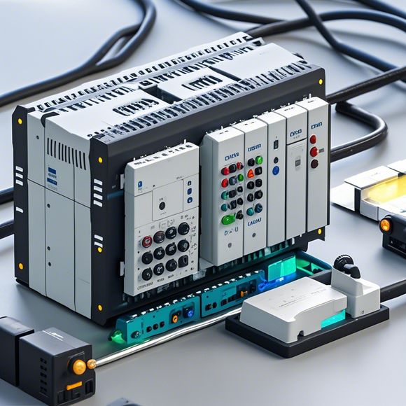
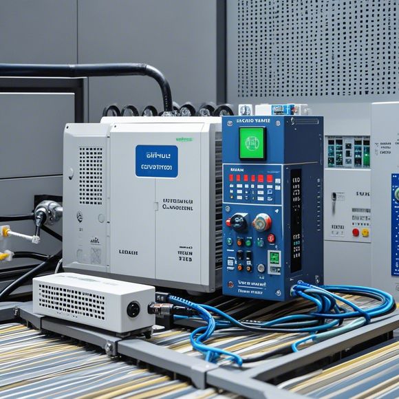
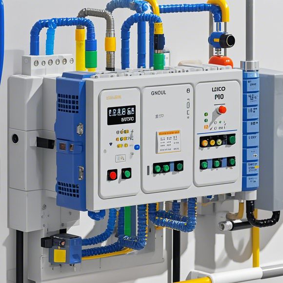
plc控制器接线图
Sure, here's a summary in English that you can use as a guide:**Summary of PID Controller Wiring Diagram:**,The purpose of a PLC (Programmable Logic Controller) is to control the flow of industrial processes. A PID controller is a type of PLC that uses three main components - Proportional, Integral and Derivative - to adjust the system response based on its current state. The diagram below illustrates how these components are connected in a typical PID controller wiring setup.- **Proportional (P)**: This component is responsible for reacting to changes in the process output and maintaining a constant level of control. When there's an error in the process, P adjusts the control signal accordingly.- **Integral (I)**: I calculates the total change in the process output over time and responds to it, not just instantaneous changes. This component smooths out disturbances by calculating the integral error, which is the sum of all past errors.- **Derivative (D)**: D provides feedback on the rate of change of the process output, allowing for quicker responses to sudden changes. It helps prevent overshooting and ensures that the control action stays within the desired limits.To connect these components, the input signals from the sensors or other process variables are sent to the PID controller, where they are processed to generate the appropriate output signals for the actuators. The wiring diagram will show the connections between the sensors, actuators, and the various control elements of the PID controller.Remember, while this is a general overview, the specific details of a wiring diagram may vary depending on the manufacturer and the specific application.
"Mastering the Art of Connecting and Controlling PLCs with an Insightful Guide to Plugging-In!"
Content:

Hey there, industry pros! Today, I'm thrilled to bring you a comprehensive guide on how to master the art of connecting and controlling PLCs. Whether you're a seasoned pro or just starting your journey in the world of industrial automation, this guide will have you up and running like a pro in no time flat. So, grab your trusty screwdrivers, get those wiring cables ready, and let's dive right into this essential skill set.
First things first, you need to have a solid understanding of what PLCs are and how they function. PLCs, also known as Programmable Logic Controllers, are digital computers that can be programmed to perform a wide range of tasks, from simple logic functions to complex process control systems. They're incredibly useful in industries such as manufacturing, energy, and even home appliances where precise timing and control are critical.
Now, let's talk about connecting PLCs to the electrical system. This is where things can get a bit tricky, but with the right tools and techniques, it's actually quite straightforward. You'll need to connect the input and output terminals of the PLC to the corresponding wiring points on the main electrical panel. Make sure to use high-quality cables rated for voltage and current, and avoid overloading the system by not exceeding the maximum capacity of each wire.

Once everything is connected up, the next step is to program your PLC. This involves writing code that defines the actions you want the system to perform. The programming language you choose depends on the type of PLC you're using, but many popular options include Ladder Logic, Function Block Diagrams, and Structured Text. Be patient and thorough when writing your code; errors can cause havoc on your system, so take your time and double-check every line.
Once your code is complete and you've confirmed that it's working correctly, all that's left is to test it out live. This involves putting the system into operation and watching its responses in real-time. If everything looks good, then you're ready to go live. Remember, however, that this is just the tip of the iceberg when it comes to PLC programming. There's always more to learn, and the possibilities are endless when it comes to creating custom solutions for specific applications in the field.
So there you have it, folks—a comprehensive guide on how to master the art of connecting and controlling PLCs. Whether you're a novice just getting started or a seasoned veteran looking to push the boundaries of your skills, this guide will give you the confidence and knowledge you need to succeed in your industrial automation endeavors. So why wait? Get plugged in and start making those circuits come alive!

Content expansion reading:
Articles related to the knowledge points of this article:
PLC Controller Wiring Guideline
PLC (Programmable Logic Controller) Control System Basics
The Role of Programmable Logic Controllers (PLCs) in Foreign Trade Operations
Connecting a PLC Controller to Your Computer
PLC Controllers: A Comprehensive Guide to Understanding Their Prices