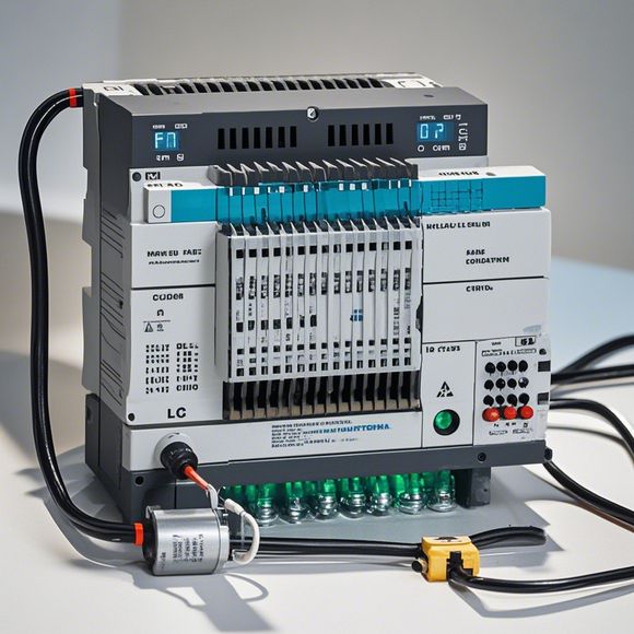
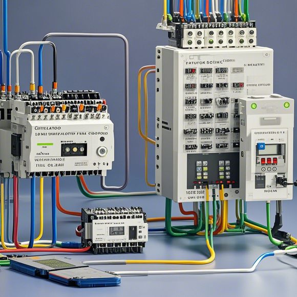
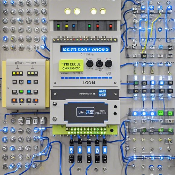
PLC Input-Output wiring diagram
A PLC (Programmable Logic Controller) is a powerful tool for automation and control systems. An I/O (Input-Output) wiring diagram is the visual representation of the connections between the various components of a PLC, such as sensors, actuators, and other devices.Here's a simple example of an input-output wiring diagram for a basic PLC system:``,+-------------+ +---------+ | |,| | | | |,| Sensor A | | Actuator A | |,| +------>+ | | +----->+ |,| | | |,| | | |,| | | |,| | | |,| | | |,| | | |,| | | |,+-------------+ +---------+ | |,| | | | |,| | | | |,| | | | |,| | | | |,| | | | |,| | | | |,| | | | |,| | | | |,+-------------+ +---------+ | |,``,In this example, Sensor A and Actuator A are connected to the same PLC input port, while Actuator A and another Sensor B are connected to different output ports. The wiring diagram shows the electrical connections between the PLC, its components, and external devices.Introduction:

As a professional in the international trade industry, understanding how to properly wire up a Programmable Logic Controller (PLC) is crucial for ensuring efficient and reliable operations. A well-designed input-output (I/O) wiring diagram can significantly reduce errors and potential downtime in production lines, automation systems, or any other PLC-driven applications. In this article, we will guide you through the process of creating an I/O wiring diagram using a PlC. We will also provide you with tips on how to interpret and understand the various components involved in this process.
Step 1: Gather Information About Your PLC
Before starting the wiring process, it's important to have a good understanding of your PLC. This includes knowing its specifications such as the number of inputs and outputs, the type of sensors and actuators that it can connect, and the programming language it supports. Additionally, you should be familiar with the manufacturer's documentation and online resources that offer detailed information about the PLC's capabilities and limitations.
Step 2: Prepare the Work Surface
Next, you need to prepare the work surface where you will be wiring up your PLC. This could mean setting up a table or desk, arranging tools and components, and ensuring there is enough lighting and ventilation to avoid accidents. You might also want to use markers to label different components so that you don't accidentally cross wires during the wiring process.
Step 3: Draw the I/O Chart

Once you have gathered all the necessary materials, start drawing your I/O chart. The chart should show the connections between the inputs and outputs of your PLC. It should include the names of each component, their respective pin numbers, and the direction of the connections. Use a diagramming program such as Visio or Proteus to help you create a visual representation of your wiring schema.
Step 4: Connect the Inputs to the Outputs
Now that you have drawn your chart, it's time to connect the inputs to the outputs. Follow the instructions provided in your PLC manual and ensure that you are connecting the right pins to the correct terminal blocks. If there are any specific guidelines or standards that you need to follow, make sure to refer to them before proceeding.
Step 5: Test the Connections
After making all the connections, it's essential to test the connections thoroughly to ensure that everything works correctly. This could involve running simulation tests or performing live testing by physically connecting the PLC to a device or system and observing its behavior. If anything seems off, take the time to troubleshoot and fix the problem.
Tips for Interpreting the Wiring Diagram:

When looking at your I/O wiring diagram, there are several things to keep in mind. Firstly, pay attention to the direction of the connections - do they go from inputs to outputs, or vice versa? This will help you understand the flow of data between your components. Secondly, be aware of the color coding used in your diagram - some manufacturers use different colors to differentiate between different functions or types of connections. Thirdly, check for any special symbols or icons used to denote certain connections or components - these may help you identify what each component is doing without having to read the manual. Finally, if possible, consult with a qualified technician to ensure that you are following proper procedures and are not overlooking any potential issues.
Conclusion:
By now, you should be well-versed in how to create and interpret a plc input-output wiring diagram. Remember that this process requires careful attention to detail, as even small mistakes can lead to significant downtime or equipment failure. With practice and experience, you'll become adept at wiring up a PLC and ensuring that your systems run smoothly. Happy wiring!
Content expansion reading:
Articles related to the knowledge points of this article:
PLC Controller Selection Guide for Foreign Trade Operations
The cost of a PLC Controller: A Comprehensive Analysis
PLC (Programmable Logic Controller) Control System Basics
The Role of Programmable Logic Controllers (PLCs) in Foreign Trade Operations