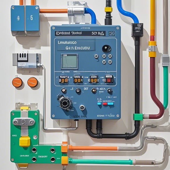
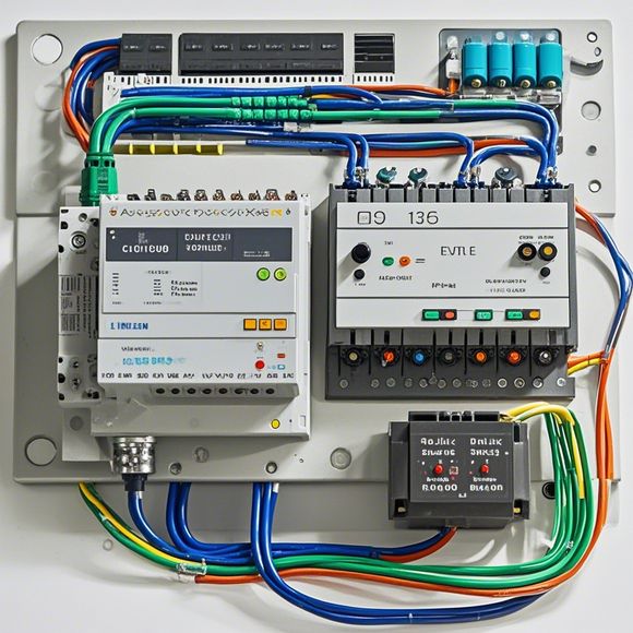
Introduction to PLC Controller Wiring Diagrams
In the world of international trade, understanding and mastering the intricacies of PLC controller wiring diagrams is crucial for ensuring successful operations. PLC (Programmable Logic Controller) controllers are a cornerstone of modern manufacturing and industrial automation, allowing for precise control of processes through digital signals. This guide aims to provide a comprehensive overview of how to interpret and use PLC controller wiring diagrams, from the fundamentals to advanced concepts.
At the heart of any PLC system lies its wiring, which consists of a complex network of wires, connectors, and terminal blocks that transmit signals between components. A typical PLC controller wiring diagram may appear daunting at first glance, but with proper understanding and practice, anyone can navigate it.
One of the most important aspects of PLC wiring is the identification of different components. These include sensors, actuators, switches, and other devices that communicate with the PLC. Each device is assigned a unique address or tag, which allows the PLC to recognize and respond to signals from these components. For example, a temperature sensor might be identified as "TEMP10," while a motor driver could be labeled "Motor_Driver2." By carefully reading and following these labels, you can quickly identify the location of each component within the PLC system.
Once you have identified the components on your wiring diagram, it's time to understand their connections. In many cases, wiring diagrams will show lines indicating the direction of signal flow between components. These lines are typically labeled with letters representing specific functions or commands, such as "INPUT" for receiving data from sensors, "OUTPUT" for outputting commands to actuators, and "STOP" for signaling an end to a particular process.

Understanding the significance of each connection requires some knowledge of electrical engineering principles. For instance, when connecting a sensor to an PLC, you need to ensure that the signal line is properly polarized to receive the correct voltage level. Additionally, you should check for any crosstalk or interference that could interfere with the signal transmission.
As your knowledge grows, you may encounter more advanced wiring configurations, including parallel connections or multiplexing schemes. To successfully manage these scenarios, you must have a firm understanding of signal levels and timing requirements. High-level wiring diagrams may also include additional symbols and codes that indicate specific functions or protocols used within the system.
One of the most critical aspects of PLC wiring is error handling. Any discrepancy in the wiring or signal flow can result in unpredictable outcomes that can disrupt production processes. Therefore, it is essential to thoroughly test your wiring before finalizing the installation. You may need to perform functional testing, diagnostic analysis, or even physical inspections to ensure that all connections are securely made and that the system operates as expected.
Another key aspect of PLC wiring is communication with other systems. Many industrial applications require PLCs to interface with other hardware devices such as HMI screens, printers, or external networks. These integrations often involve using specialized communication protocols such as PROFINET or EtherCAT. It is important to understand these protocols and how they interact with the PLC's internal logic to ensure seamless data transfer and control over various systems.

Finally, one of the most challenging aspects of PLC wiring is troubleshooting. When something goes wrong, it can be difficult to pinpoint the source of the problem without access to the actual wiring diagram. However, by studying common issues and their solutions, you can become proficient in identifying and fixing problems quickly. This includes understanding how to troubleshoot faulty sensors, damaged circuitry, or software glitches that may be causing issues with your PLC system.
In conclusion, PLC controller wiring diagrams are a complex yet essential aspect of industrial automation. By mastering their interpretation and application, you can confidently navigate the intricacies of your PLC system and ensure smooth operation of your production processes. With patience and dedication, anyone can become a skilled PLC wiring expert and take their industrial automation to new heights.
Content expansion reading:
Articles related to the knowledge points of this article:
Smart Manufacturing Solutions with PLC Integrated Machinery
The cost of a PLC Controller: A Comprehensive Analysis
PLC Programming for Automation Control in the Manufacturing Industry
PLC (Programmable Logic Controller) Control System Basics
Plumbers Rule! The Role of PLC Controllers in the World of Waterworks
The Role of Programmable Logic Controllers (PLCs) in Foreign Trade Operations