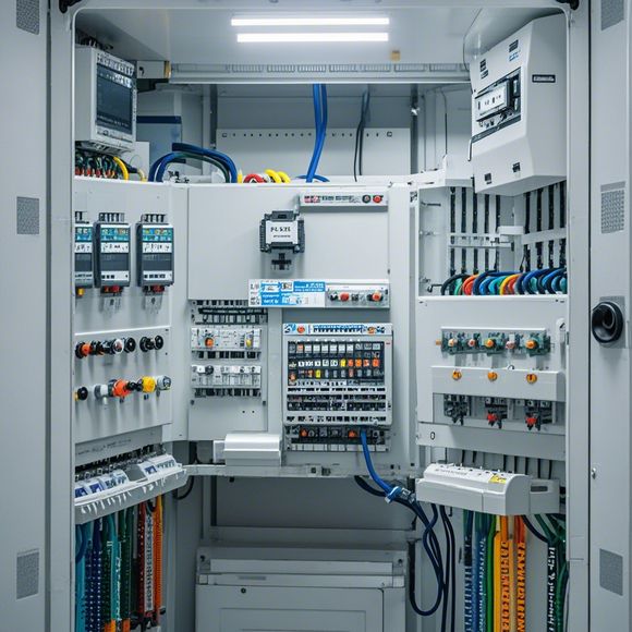
PLC Input/Output Connection Diagram
Sure, I can help you generate a summary for a PLC (Programmable Logic Controller) input/output connection diagram. Here's an example:---**Summary: PLC Input/Output Connection Diagram**In this diagram, we represent the connections between various components in the PLC system. The primary components include the PLC itself, sensors, actuators, and other devices that need to be controlled by the PLC.The PLC is connected to the input/output ports through a series of wires. Each input/output port has its own pins, which are connected to specific sensors or actuators. These connections are represented by solid lines.Some sensors and actuators have their own dedicated inputs and outputs, which are indicated by dashed lines. This allows us to connect multiple sensors or actuators to the same input/output port on the PLC.The connections between the sensors and actuators are also shown, but only if they have specific functions or requirements that need to be considered.Overall, this diagram provides a clear overview of how the PLC system is designed to control various components, ensuring that all connections are properly established and tested before deployment.
Dear friends, today I would like to discuss with you about the PLC (Programmable Logic Controller) input/output connection diagram. As a professional in the field of foreign trade, I have seen many different kinds of plc systems used for various applications. The PLC input/output connection diagram is an important part of the system design and operation process.
Firstly, let's understand what the PLC input/output connection diagram is. It is a detailed representation of all the connections between the PLC, the sensors or actuators that it controls, and the other components of the control system. This diagram helps us to identify and understand the relationships between the components and how they communicate with each other.
Now, let's talk about the importance of the PLC input/output connection diagram. First of all, without this diagram, it is impossible for us to understand the functionality and behavior of a PLC system. We need to be able to read and interpret the diagram to determine the signals that will be sent from one component to another and the actions that will be taken based on those signals.
Moreover, the PLC input/output connection diagram is also very helpful in troubleshooting and maintenance. When there are issues with the system, we can refer to the diagram to determine where the problem might be located and how to fix it. Additionally, during the installation and setup of the system, we use this diagram to ensure that all the components are correctly connected and that the connections are secure.

Another advantage of this diagram is its flexibility. With modern PLC systems, there are many different types of inputs and outputs that can be used. The diagram helps us to understand how these different types of inputs and outputs can be integrated into the system to achieve the desired results.
In addition, this diagram also provides guidance on safety practices. For example, we need to make sure that the connections are made securely and that there is no possibility of short circuits. This ensures that the PLC system operates safely and efficiently.

Finally, the PLC input/output connection diagram is an essential tool for any professional in the field of automation. It helps us to ensure that our systems are reliable, efficient and safe. So if you are a professional in the field of foreign trade, it is important to learn how to use this diagram properly and effectively.
In conclusion, the PLC input/output connection diagram is a critical part of any PLC system design and operation. It provides us with a clear understanding of how the components interact and communicate, helping us to troubleshoot and maintain the system effectively. So don't forget to take some time to learn more about this diagram and how it can benefit your own work as a foreign trade professional.

Content expansion reading:
Articles related to the knowledge points of this article:
PLC Controller Wiring Guideline
PLC Programming for Automation Control in the Manufacturing Industry
The Role of Programmable Logic Controllers (PLCs) in Foreign Trade Operations
PLC Controllers: A Comprehensive Guide to Understanding Their Prices