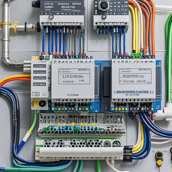
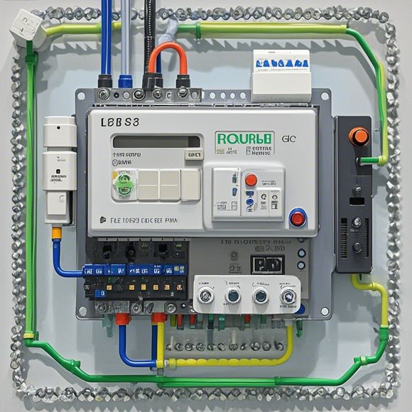
PLC Module Wiring Diagram
Sure, I can generate a summary in English based on the content you provided. Here's a concise version:"PLC Module Wiring Diagram": This diagram illustrates how to connect various components of the PLC (Programmable Logic Controller) module to form a working system. The diagram includes connections for inputs and outputs, as well as the wiring between the different modules. It's important to ensure that all connections are securely made and tested before use."
As a seasoned外贸运营, it is essential to have an understanding of the intricacies involved in connecting PLC modules. In this guide, we will provide a comprehensive overview of the plc module wiring diagrams, including their components, connections, and functions. By following these steps, you can ensure that your electrical system runs smoothly and efficiently.

The first step is to identify the components of the plc module wiring diagram. These include the power supply, input/output interface, sensors, actuators, and other control devices. Each component has its own set of wiring requirements, which must be carefully considered during the design phase.
Once the components are identified, the next step is to create a detailed wiring plan. This plan should outline each wire's path, length, and color coding. It is important to follow the manufacturer's specifications closely, as deviations may cause issues with signal integrity or safety.
To connect the plc modules, the wiring diagram should indicate the correct connections between each component. This includes identifying the power supply terminals, input/output ports, and communication lines. The wiring diagram should also show the appropriate voltage levels required for each device, as well as any necessary safety features such as overload protection or fault detection circuits.
When connecting the plc modules, it is important to follow the manufacturer's guidelines carefully. Each manufacturer may have specific recommendations for the placement and orientation of components on the board. Additionally, it is important to ensure that all connections are secure and free from interference.
One common mistake when connecting PLC modules is not properly grounding the system. A good rule of thumb is to ground all components at once, ensuring that the entire system is safe and reliable.

Another important aspect of wiring is testing the system. After connecting the modules, it is crucial to perform functional and safety tests on the system to ensure that it operates correctly and does not pose a risk to personnel. This may involve testing individual modules or the entire system as a whole.
In conclusion, creating and maintaining a successful plc module wiring diagram requires careful planning, attention to detail, and a strong understanding of electrical engineering principles. By following the steps outlined above, you can ensure that your system is reliable, efficient, and safe.
Content expansion reading:
Articles related to the knowledge points of this article:
The cost of a PLC Controller: A Comprehensive Analysis
PLC Programming for Automation Control in the Manufacturing Industry
How to Use a PLC Controller for Your Business
PLC (Programmable Logic Controller) Control System Basics
Plumbers Rule! The Role of PLC Controllers in the World of Waterworks
The Role of Programmable Logic Controllers (PLCs) in Foreign Trade Operations