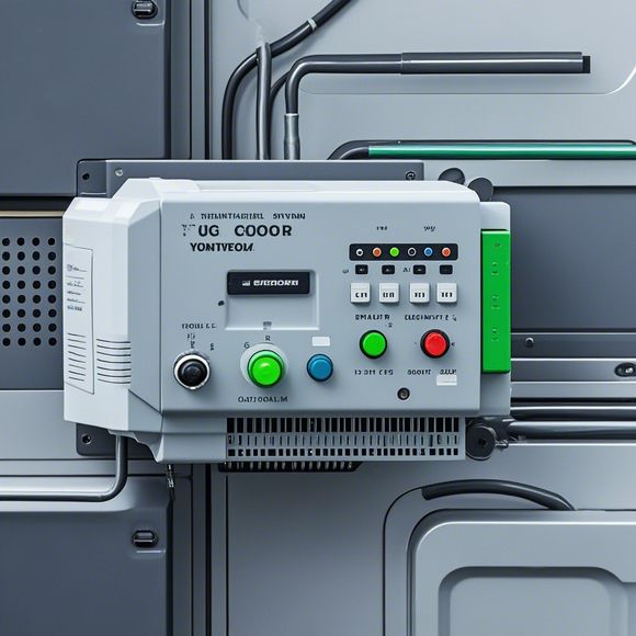
PLC Controller Wiring Diagrams: A Comprehensive Overview for Your Business
Sure, here's a concise summary in English that encapsulates the key points you provided:"PLC (Programmable Logic Controller) controller wiring diagrams are essential for businesses to ensure proper electrical connections and efficient operation. A comprehensive wiring diagram provides a clear visual representation of the electrical connections between different components, including sensors, actuators, and control panels. It helps in identifying potential issues early on, reducing downtime and ensuring compliance with safety regulations. By having a well-designed wiring diagram, businesses can optimize their electrical systems, save on maintenance costs, and improve overall efficiency. Therefore, investing time and resources into creating accurate and detailed wiring diagrams is crucial for the success of any industry."
Dear colleagues,
As we navigate the vast world of international trade, understanding how our PLC (Programmable Logic Controller) controllers function is crucial to ensure smooth operations and efficient performance. Today, I will guide you through a detailed explanation of the plc controller wiring diagrams, covering everything from basic concepts to advanced configurations, tailored to suit your business needs.

Firstly, let's delve into the basics. A plc controller is an industrial control system that automates various processes in factories or other manufacturing setups. It operates on a set of pre-programmed logic, enabling it to respond to specific events such as sensor data, actuator commands, and timer triggers. The success of any automation system hinges on its ability to communicate effectively with the hardware components that it controls—which is why wiring diagrams play a fundamental role.
Now, onto the wiring diagram itself. It represents the physical connections between various components within the plc system, such as sensors, switches, actuators, and other digital devices. Each component's input and output pins are marked with letters and digits, indicating their functions and locations in relation to each other. This notation is essential for troubleshooting and maintenance, as it allows us to quickly identify which parts need attention without having to physically disassemble the system.
The first step in understanding a wiring diagram is to recognize the different types of connections, such as direct current (DC) connections, alternating current (AC) connections, and power supplies. Direct DC connections involve connecting wires directly between two components, while AC connections require a dedicated transformer or amplifier circuit. Power supplies provide a stable voltage source for the plc controller, ensuring that it can operate without interference or malfunction.
Next, we look at the various components that make up the wiring diagram, including the main components themselves, along with their respective connections. The main components include the CPU (Central Processing Unit), RAM (Random Access Memory), and ROM (Read-Only Memory). These components store the program instructions and perform calculations based on inputs from the sensors and actuators.
Sensors and actuators are also critical components in a plc system, providing real-time feedback on conditions such as temperature, pressure, and motion. They send signals back to the plc controller, allowing it to respond accordingly. Similarly, relays serve as an intermediate step in the signal transmission process, converting electrical signals into mechanical actions like opening and closing switches and moving motors.

Now let's delve deeper into some advanced configurations. One common scenario involves the use of multiple plc controllers operating in parallel. This approach enables simultaneous processing of multiple tasks, increasing production efficiency. Another example is the integration of PLCs with other types of automation systems, such as HMI (Human Machine Interface) panels or SCADA (Supervisory Control And Data Acquisition) systems.
Finally, let's talk about the importance of safety features in a plc system. Many modern controllers come equipped with emergency stop buttons, fault detection circuits, and overload protection mechanisms. These features ensure that the system remains safe even under extreme conditions, preventing potential accidents and downtime.
In conclusion, understanding the wiring diagram of a plc controller is key to ensuring efficient and reliable operation. By following these guidelines and consulting with professionals in the field, you can navigate complex installations and maintain your business's competitive edge. Remember, a well-maintained plc system can save time, money, and resources, making your business more profitable and sustainable.
Content expansion reading:
Articles related to the knowledge points of this article:
The Role of Programmable Logic Controllers (PLCs) in Foreign Trade Operations
PLC Controllers: A Comprehensive Guide to Understanding Their Prices
Effective Strategies for Handling PLC Control System Faults
What is a Programmable Logic Controller (PLC)
PLC Controller Advantages: A Comprehensive Guide for Success in Global Trade
Mastering the Art of PLC Control: Unlocking Industry-Grade Automation Powerhouses