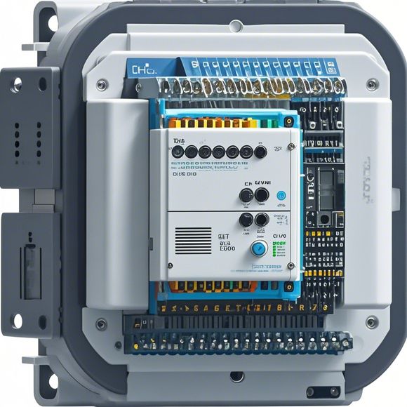
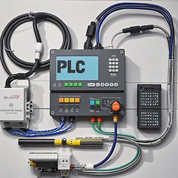
PLC Controller Principle Diagram
The PLC (Programmable Logic Controller) is a device that allows you to program and control various types of devices. It's designed to make it easy for engineers, technicians, and operators to control and monitor industrial processes. The principle diagram of the PLC controller typically shows how different components are connected and how they interact with each other.In this diagram, you can see the input and output modules, which are responsible for receiving and sending signals to and from the process. The central processing unit (CPU) is where the actual logic of the PLC is located. It takes in signals from the input module and performs calculations based on predefined algorithms or user-defined programs. Then, it outputs commands to the output modules, which control the actuators and sensors that are used in the industrial process.The PLC also has communication capabilities, allowing it to connect to other devices and networks through Ethernet or other communication protocols. This makes it possible to monitor and control processes remotely, and to send and receive data from other sources.
Hello, everyone! Today, I'm excited to talk about the principle diagram for PLC controllers. If you're a newbie in this field or someone interested in learning more about it, this is going to be a great introduction. So let's dive right in and take a closer look at what we're discussing.

Firstly, a PLC (Programmable Logic Controller) is a device that allows you to control your industrial processes using a computer program. It can handle all sorts of tasks, like lighting up an assembly line with just a few simple commands, monitoring temperatures in your factory, or controlling robotic arms. And guess what? All of these things are made possible by this incredible piece of hardware.
Now, when it comes to understanding how these PLCs work, there are three main components to keep in mind: input devices, output devices, and a central processing unit. Input devices, also known as sensors or sensors, are used to detect physical changes in the environment around the PLC. For example, if a temperature sensor detects a rise in temperature, it sends a signal to the PLC. The same goes for other types of inputs like pressure sensors, speed sensors, etc. Output devices, on the other hand, involve the physical actions that the PLC will take based on the signals from its input devices. For example, if a motor is being controlled by an PLC, the PLC might turn on or off the motor based on the signal from the sensor.

And finally, let's talk about the CPU (Central Processing Unit). This is where all the magic happens. The CPU receives the signals from the input devices and decides what actions should be taken based on those signals. Depending on the type of task you're trying to accomplish, the CPU can make decisions quickly and accurately, allowing you to control your industrial processes with precision.
So there you have it, folks! A brief overview of how PLC controllers work. If you're still feeling a bit overwhelmed, don't worry, because there's always more to learn! But for now, let's take a deep breath and get started with our first step towards mastering this powerful technology.

Content expansion reading:
Articles related to the knowledge points of this article:
PLC Controller for Manufacturing Automation
PLC (Programmable Logic Controller) Control System Basics
The Role of Programmable Logic Controllers (PLCs) in Foreign Trade Operations
Effective Strategies for Handling PLC Control System Faults
PLC Controller Advantages: A Comprehensive Guide for Success in Global Trade
Mastering the Art of PLC Control: Unlocking Industry-Grade Automation Powerhouses