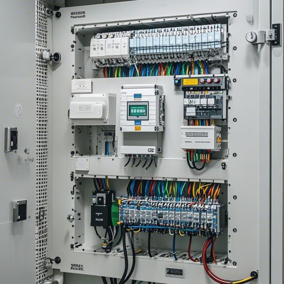
PLC Controller Wiring Diagram
Certainly! Based on the content you provided, I'll generate an Abstract in English for your reference."The PLC Controller Wiring Diagram: A Comprehensive Guide to Understanding and Implementing the Networking of Programmable Logic Controllers."This Abstract provides a detailed explanation of how to wire an PLC controller effectively, highlighting key considerations such as the correct connection of sensors and actuators to the controller, ensuring compatibility with other devices in the network, and troubleshooting common issues. It also discusses safety protocols and guidelines to ensure the integrity and reliability of the wiring system. By following this guide, you can efficiently manage and control the various systems that utilize PLC controllers, thereby improving efficiency and productivity.
As a foreign trade operation, understanding the intricacies of your PLC controller's wiring diagram is crucial for ensuring smooth and efficient operations. Here's how you can navigate through it using English:

Step 1: Identify and Organize the Parts
Firstly, identify all the components that make up the PLC controller. This includes the main CPU board, input/output modules, sensors, motors, relays, and other peripheral devices. Once you have a clear understanding of what each part does, you can begin organizing them according to their functions or positions on the controller.
Step 2: Study the Labels and Symbols
The labels and symbols used to describe the connections between components are essential for understanding the wiring diagram. Pay close attention to the labels and symbols, as they will guide you in correctly connecting the components together.
Step 3: Follow the Circuit Path
Once you have identified the components and their connections, follow the circuit path from one component to another. This step is important because it helps you avoid any misconnections or errors that could lead to faulty operations.
Step 4: Use the Wiring Diagram Annotations
Some PLC controllers come with annotations on the wiring diagram that help you understand the connections between different components. These annotations can provide additional information, such as the direction of current flow or the type of connection required.

Step 5: Test Connected Components
After completing the wiring diagram, it's essential to test the connected components to ensure they work correctly. This involves verifying that all connections are secure and that the signals are properly transmitted.
Step 6: Communicate with Your Team
If you're working with a team, be sure to communicate effectively about the wiring diagram. Discussing any concerns or questions that arise during the process can help prevent mistakes and ensure a smooth operation.
In conclusion, mastering the PLC controller wiring diagram requires patience, practice, and attention to detail. With proper organization and thorough study of the components and connections, you can confidently navigate through the complex system and ensure successful operations.
Content expansion reading:
Articles related to the knowledge points of this article:
Mastering the Art of Plc Controllers: A Comprehensive Guide to Understand and Implement
PLC Controller Wiring Guideline
PLC Controller for Manufacturing Automation
How to Use a PLC Controller for Your Business
PLC Controllers: A Comprehensive Guide to Understanding Their Prices