Understanding and Connecting the PlC Control Cabinet Wire Diagram: A Guide for Beginners
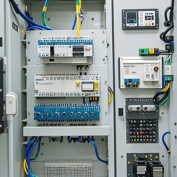
In this guide, we will walk you through the process of understanding and connecting the PLC control cabinet wire diagram. This is a great opportunity for beginners to learn about the intricacies of electrical wiring in automation systems.Firstly, it's important to understand the basic components of the PLC control cabinet. This includes the CPU, input/output modules, memory, and other essential electronic devices that make up the system. Once you have a clear understanding of these components, you can begin to connect them together.The wire diagram is a visual representation of the connections between these components. It typically shows the connections from the inputs to the outputs, as well as any additional components such as relays or sensors. To properly connect the wires, it's important to follow the diagram step-by-step, ensuring that each connection is secure and that all wires are routed correctly.Finally, it's crucial to test the entire system before turning it on for production use. This involves verifying that all connections are functioning correctly and that the system is safe to operate. With proper training and practice, even beginners can become proficient in the art of wire management within an PLC control cabinet.
Introduction:
Welcome to our tutorial on how to understand and connect the plc (programmable logic controller) control cabinet wire diagram. This guide is designed to help you become an expert in handling and configuring your PLC system, ensuring smooth operation and maximum efficiency. We’ll start by explaining the basic components of a plc system, then move on to the key points of each wire in the wiring diagram. Finally, we’ll walk you through the steps involved in connecting all the pieces together. By the end of this tutorial, you’ll have a solid understanding of how to tackle complex wiring tasks and ensure your PLC system works like clockwork. So let’s get started!
Components of a PlC System:

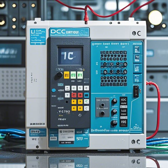
Before we dive into the wiring diagram, it’s important to first understand the core components of a plc system. Here they are:
1、Central Processing Unit (CPU): The brain of the plc, which processes data received from sensors and motors and sends commands to other units in the system.
2、Input/Output Module (I/O): These modules provide interface between the CPU and external devices such as switches, relays, or input devices.
3、Programmable Logic Controller (PLC) Software: This software manages the flow of information between the hardware components and provides functionality like error checking, diagnostics, and user interfaces.
4、Fieldbus Interface: This enables communication between different systems within the same factory or plant.
5、Network Interface: If the plc is part of a larger network, this interface allows it to communicate with other devices on the network.
Key Points of Each Wire:
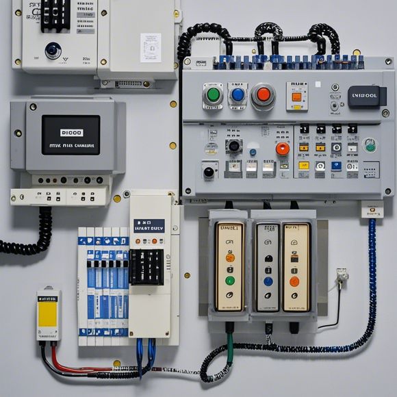
Now that we’ve covered the basic structure of a plc system, let’s look at the specific wire connections in the wiring diagram. Each wire has its own unique function and should be handled with care. Here are some key points:
1、Power Connections: These include power leads that supply electricity to the plc and its associated components. They should be routed carefully to avoid overheating or short circuits.

2、Data Connections: These include wires that carry signals between the CPU and other components like I/O modules or fieldbus interfaces. These connections should be clean and free of any damage or interference.
3、Grounding Wires: Grounding is essential for safety purposes. Make sure all grounding wires are securely connected and follow the manufacturer's instructions for proper grounding practices.
4、Control Connections: These wires allow for the transmission of control signals from the CPU to various actuators like motor controllers or relays. They must be carefully routed to avoid crosstalk and interference.
5、Test Connections: These wires are used for testing purposes before finalizing the wiring. They should be disconnected when not in use to prevent damage or accidental activation of the system.
Steps Involved in Connecting All Pieces Together:
Now that we’ve discussed the key points of each wire, let’s take you through the steps involved in connecting them together. This process may vary slightly depending on the specific model of plc you're working with but generally follows these steps:
1、Gather all necessary tools and materials: You'll need wire strippers, cable crimpers, connectors, and other tools to perform the task safely. Also, make sure you have the appropriate size and type of wires for your system.
2、Disconnect any existing connections: Before starting, make sure all existing connections are disconnected from their original locations. This helps prevent any damage to sensitive components or equipment during the wiring process.
3、Locate all components: Carefully locate the CPU, I/O modules, fieldbus interface, network interface, and other components in your system. This will help you identify where each component needs to be connected.

4、Determine the sequence of connections: Based on the wiring diagram, determine the order in which you want to connect each wire. This helps you avoid mistakes and ensures that all wires are routed properly.
5、Connect each piece: Follow the diagram carefully and connect each wire to its corresponding component. Ensure that connections are secure and free of any damage or interference.
6、Test the system: After completing all connections, test your system thoroughly to ensure it functions as expected. Check for any errors or issues and make any necessary adjustments before moving forward.
7、Clean up: Once everything is connected and tested, remove all wires and tools from the system. Clean up any debris or leftover materials to maintain a neat and organized work area.
Conclusion:
By now, you should be well-acquainted with how to understand and connect the plc control cabinet wire diagram. Remember, patience and attention to detail are crucial when working with complex electrical systems like plc systems. With practice, mastery of these skills will come naturally, and you'll find yourself confidently tackling even more challenging wiring tasks in the future. Happy debugging!
Content expansion reading:
Articles related to the knowledge points of this article:
The cost of a PLC Controller: A Comprehensive Analysis
PLC Programming for Automation Control in the Manufacturing Industry
How to Use a PLC Controller for Your Business
Plumbers Rule! The Role of PLC Controllers in the World of Waterworks