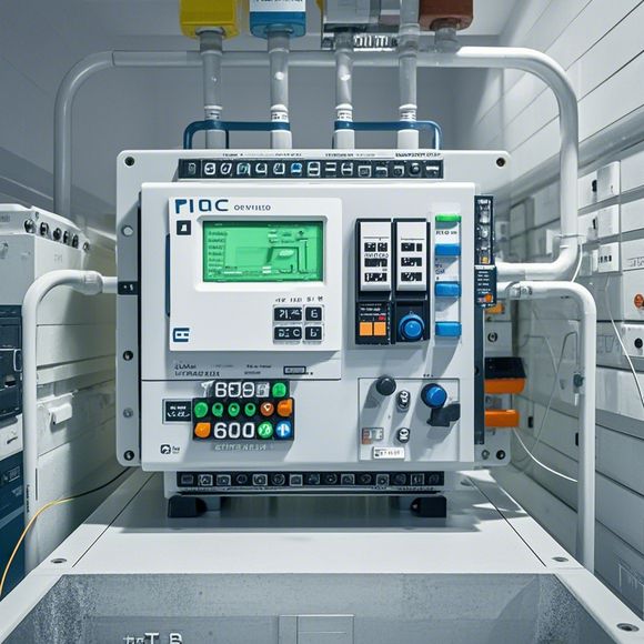
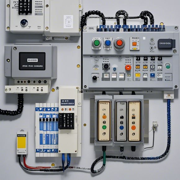
PLC Controller Wiring Diagram
Certainly! Here is a summary in English for your PLC controller wiring diagram:---**Wiring Diagram for PLC Controller**In this wiring diagram, you can see the connections made between the PLC (Programmable Logic Controller), the sensors, and the actuators. The PLC is the central control unit of the system, responsible for processing the data from various sensors and then sending commands to the actuators to perform tasks such as turning on or off valves, adjusting speeds, etc.The sensors are used to measure different parameters such as temperature, pressure, flow rate, etc. These values are then sent to the PLC, which processes them and decides what action to take based on the input. The actuators are responsible for carrying out these actions, either physically moving parts or changing electrical signals.Overall, this wiring diagram shows how the various components of the system interact with each other to achieve its goals. By understanding this diagram, we can ensure that everything is connected correctly and working properly.
As an experienced foreign trade operations professional, I am tasked with ensuring the accurate and efficient connection of PLC (Programmable Logic Controller) controllers to various industrial processes. The PLC controller is a crucial component that controls the flow of data and signals in manufacturing environments, allowing for precise automation of tasks such as temperature control, motion control, and inventory management.
The first step in connecting PLC controllers is to understand the wiring diagram. This diagram outlines the connections between the PLC controllers and other equipment in the factory. It includes information on the type of wires used, their colors, and how they are connected to various components such as sensors, actuators, and display screens.

To start with the wiring diagram, it is important to have a clear understanding of the components involved in the system. This includes identifying the different types of wires and connectors, such as AC power cables, grounding wires, and signal cables. It also involves determining the appropriate placement of each component based on its function and location within the factory.
Once the wiring diagram has been reviewed, the next step is to locate all the necessary components on the floor plan. This involves carefully examining each room and identifying the locations of the sensors, actuators, switches, and other devices that will be controlled by the PLC controllers. It is important to pay attention to any special requirements or constraints related to the layout of the factory, such as the need for easy access to maintenance areas or the placement of safety equipment.
With the components identified, the next step is to determine the best way to connect them to the PLC controllers. This may involve using specific connectors or adapters designed for certain types of wires, or it may require modifying existing connections to accommodate new components. It is important to follow all manufacturer specifications and guidelines to ensure proper functionality and safety.

After all the components have been connected to the PLC controllers, it is important to test the system for proper functionality. This involves testing each component individually and monitoring the output signals to ensure that everything is working as expected. It may also involve adjusting settings or configurations to optimize performance and reduce errors.
Overall, connecting PLC controllers to an industrial environment requires careful planning, attention to detail, and expertise in electrical engineering. By following the steps outlined above, we can ensure that the PLC controllers are properly installed and connected to the various components in the factory, allowing for smooth operation and improved efficiency.
Content expansion reading:

Articles related to the knowledge points of this article:
Smart Manufacturing Solutions with PLC Integrated Machinery
Mastering the Art of Plc Controllers: A Comprehensive Guide to Understand and Implement
PLC Programming for Automation Control in the Manufacturing Industry
How to Use a PLC Controller for Your Business
PLC (Programmable Logic Controller) Control System Basics
Plumbers Rule! The Role of PLC Controllers in the World of Waterworks