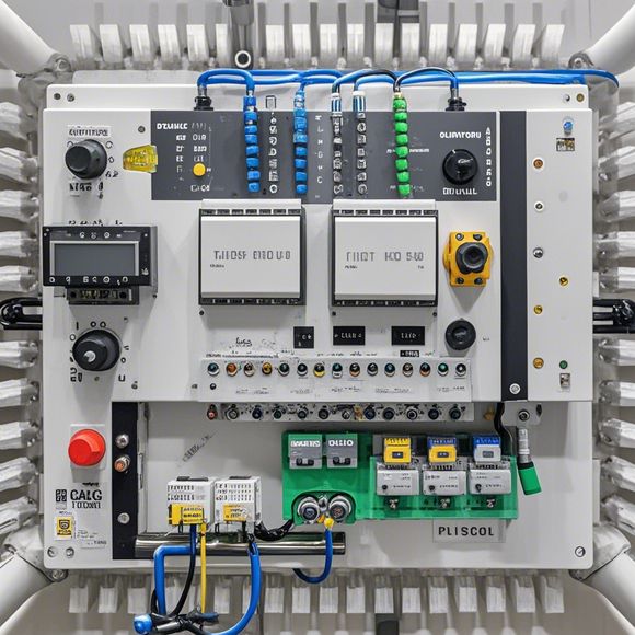
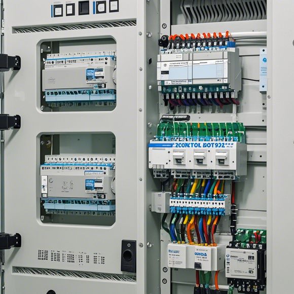
PLC Control Cabinet Wiring Diagrams
Sure, I can help with that. Can you please provide me with the content or any other specifics you would like to include in your summary?
Introduction: Welcome to our comprehensive guide on the plc (programmable logic controller) control cabinet wiring diagram. This guide aims to provide a detailed understanding of how to connect various components and devices to form a complete system for controlling industrial processes. Whether you are a seasoned engineer or a beginner, this guide will help you navigate through the complex world of PLC programming and wiring.
Step 1: Understanding the Basics

Before we dive into the details of wiring, it is important to understand the basics of PLC systems. A PLC is a powerful tool that allows for precise control over industrial processes. It works by processing information from input devices such as sensors and actuators, then using this data to make decisions based on preset rules. The resulting actions are sent to output devices, such as motors and lights, to control the overall flow of the process.
Step 2: Analyzing the Wiring Diagram
Once you have an understanding of the basics, the next step is to analyze the wiring diagram itself. Each component has a unique position in the system, and each wire has a specific function. Here are some key elements you should pay close attention to:
Input Devices: These are devices that generate data that will be used to make decisions in the program. Examples include sensors, switches, and actuators.
Output Devices: These are devices that will respond to the decisions made by the program. Examples include motors, lights, and other equipment.

PLC Controller: This is the brain of the system, responsible for interpreting the input data and making decisions based on preset rules.
Power: All electrical components need power, so you must ensure that all connections are securely made and that the appropriate voltage levels are being applied.
Data Communication: Many systems use protocols like IEC 61131-3, which define the structure and syntax of the communication between different components. Be sure to follow these standards.
Step 3: Building Your Wiring Diagram
Now that you have a clear understanding of what each component does, you can start building your own wiring diagram. Start by creating a rough sketch of the system, then refine it based on the specific needs of your project. Use diagramming software to create the final layout. Make sure to label each component clearly and follow the guidelines provided in the manual or documentation for your particular PLC system.

Step 4: Testing Your System
After completing your wiring diagram, it is essential to test the entire system to ensure everything is working correctly. This includes verifying that all inputs are properly connected to their corresponding outputs, checking for proper power supply, and confirming that the program is running smoothly. If there are any issues, take time to troubleshoot and correct them before moving forward with the next steps.
Conclusion: By following these steps, you should be able to successfully build and test a PLC control cabinet with a detailed wiring diagram. Remember, this is just one example of what can be achieved with careful planning and execution. With practice and experience, you will become an expert in PLC programming and wiring, allowing you to control even more complex industrial processes with ease.
Content expansion reading:
Articles related to the knowledge points of this article:
The cost of a PLC Controller: A Comprehensive Analysis
How to Use a PLC Controller for Your Business
PLC (Programmable Logic Controller) Control System Basics
Plumbers Rule! The Role of PLC Controllers in the World of Waterworks
The Role of Programmable Logic Controllers (PLCs) in Foreign Trade Operations