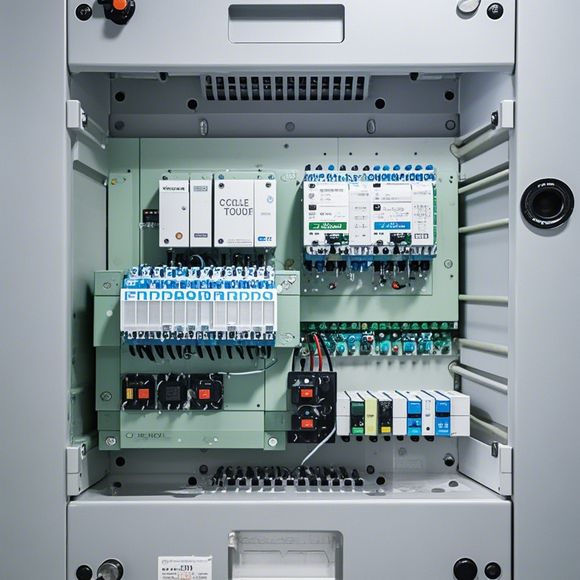
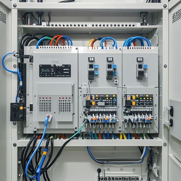
PID Controller Principle Diagram in English
PID Controller Principle Diagram:The PID controller is a type of control system used to maintain a steady state in a process. It consists of three main parts: Positive Integral (P), Proportional (I), and Differential (D). The P component calculates the error between the current state of the system and the desired state, while the I component adjusts the system by adding a small amount to the output if the error is large. Finally, the D component adjusts the system by subtracting the same amount from the output if the error is negative. This combination of components allows for a more stable and efficient response to changes in the system state.
In the world of international trade, understanding how to operate and maintain a plc (programmable logic controller) system is crucial for any business that relies on automation. A PID (Proportional-Integral-Derivative) controller is a type of control system used to regulate the output of an industrial process based on feedback from sensors. By adjusting the three components of the PID controller—proportional, integral, and derivative—it can effectively handle changes in the process and maintain stability in response to disturbances or variations. In this article, we will discuss some key aspects of the PID control principle diagram in English and provide insights into its practical application in different industries.
The PID controller consists of three main parts: proportional, integral, and derivative. The proportional part adjusts the output based on the difference between the current value and the desired value. This component is designed to quickly react to changes in output and minimize overshoots. The integral part calculates the total error by summing up the differences between the current value and the desired value, which helps to smooth out long-term deviations. Finally, the derivative part provides information about the rate of change in the output and helps to detect trends and anticipate future changes.
When designing the PID controller, it is important to understand how these three parts interact with each other and their individual functions. For example, in a temperature control system, the proportional part might be set high to ensure rapid response to changes in output temperature, while the integral part may be adjusted to compensate for long-term drift caused by heat sources. The derivative component could be used to monitor changes in temperature over time and adjust the controller accordingly.
One common use case for PID control is in HVAC systems (Heating, Ventilation, and Air Conditioning). In such applications, the controller adjusts the flow of air through vents based on the temperature detected by thermostats and humidity sensors. By setting the PID parameters according to the specific requirements of the building's environment, the system can efficiently maintain a comfortable temperature range for occupants. Additionally, PID controllers are also used in manufacturing processes where they help to optimize production line speeds and reduce downtime due to machine maintenance or breakdowns.

Another industry where PID controllers play a critical role is in robotics. In this context, the controller controls the movements of robot arms and legs based on the position and force exerted by the end effector. By adjusting the PID parameters according to the task requirements and the dynamic nature of the workload, the robot can accurately perform tasks with minimal errors and maximize productivity.
In addition to their applications in industrial environments, PID controllers are also used in consumer electronics. For example, in automotive applications, PID controllers are used to control the throttle angle of engine valves based on sensor signals from accelerator pedal input and vehicle motion. By adjusting the PID parameters accordingly, the controller ensures that the engine operates efficiently and smoothly without causing excessive fuel consumption.

In summary, the PID control principle diagram is a vital tool for anyone operating a plc system. By understanding the various components of the PID controller and how they interact, businesses can optimize their processes and improve efficiency and reliability. Whether it's controlling temperature in a building or regulating engine throttle angles in a vehicle, the power of a well-designed PID controller cannot be underestimated. As such, cultivating a deep understanding of this technology is essential for anyone seeking to succeed in their field.
Content expansion reading:

Articles related to the knowledge points of this article:
PLC Programming for Automation Control in the Manufacturing Industry
How to Use a PLC Controller for Your Business
Plumbers Rule! The Role of PLC Controllers in the World of Waterworks
Connecting a PLC Controller to Your Computer