Understanding PLC Circuit Diagrams through a Graphic Guide
通过图形指南理解可编程逻辑控制器(PLC)电路图As a professional engineer, I often deal with complex circuit diagrams of Programmable Logic Controller (PLC) systems. To better understand these diagrams, I have found that using a graphic guide can be an effective way to simplify the process.The graphic guide provides visual cues and symbols that help identify different components, connections, and functions within the PLC circuit. By following the guide's instructions, one can quickly locate the specific components they need to troubleshoot or design their own circuits.Additionally, the graphic guide often includes diagrams and illustrations that show how different circuit components interact with each other. This information is invaluable when working with complex PLC systems, as it helps engineers avoid common mistakes and ensure proper circuit function.Overall, using a graphic guide when learning or working with PLC circuit diagrams can greatly enhance one's understanding and efficiency. It is a valuable resource for anyone looking to master this important technology.
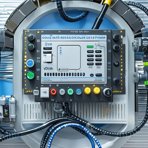
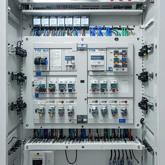
As an experienced trader, understanding the intricacies of the PLC (Programmable Logic Controller) circuit diagrams can be a daunting task for those who are new to the field. The intricate nature of these diagrams can make it difficult to grasp the underlying logic and functionality at first glance. However, with the right tools and knowledge, one can quickly navigate through the complexities of the PLC world. In this guide, we will take you on a visual tour of the PLC circuit diagrams, helping you understand each component and how they work together to control and monitor industrial processes.
To start off, let's break down the components that make up a standard PLC circuit diagram. There are several key parts that need to be identified to fully comprehend the system's operation:
1、Input/Output Devices: These are devices that receive input from the outside world or send output to external devices. They include sensors, switches, relays, and other hardware components that interface with the PLC.

2、Process Control: This is where the real magic happens. The programmable logic within the PLC determines when, what, and how much of each process variable should change based on predefined conditions.
3、Memory and Processing Unit: The PLC's central processing unit (CPU) stores programs that control the flow of data through the various inputs and outputs. It also has memory to store variables and data points that are used by the CPU during processing.

4、Power Supply: A reliable power supply is essential for maintaining the stability of the entire system. The PLC requires a stable voltage and current supply to operate properly.
Now let's look at an example circuit diagram. Let's say we have a simple PID temperature control loop. Here's how the diagram might look like:

[ ] |--[ ] [ ] [ ] [ ] [ ] [ ] [ ] [ ] [ ] [ ] [ ] [ ] [ ] [ ] [ ] [ ] [ ] [ ] [ ] [ ] [ ] [ ] [ ] [ ] [ ] [ ] [ ] [ ] [ ] [ ] [ ] [ ] [ ] [ ] [ ] [ ] [ ] [ ] [ ] [ ] [ ] [ ] [ ] [ ] [ ] [ ] [ ] [ ] [ ] [ ] [ ] [ ] [ ] [ ] [ ] [ ] [ ] [ ] [ ] [ ] [ ] [ ] [ ] [ ] [ ] [ ] [ ] [ ] [ ] [ ] [ ] [ ] [ ] [ ] --[ ] --[ ] --[ ] --[ ] --[ ] --[ ] --[ ] --[ ] --[ ] --[ ] --[ ] --[ ] --[ ] --[ ] --[ ] --[ ] --[ ] --[ ] --[ ] --[ ] --[ ] --[ ] --[ ] --[ ] --[ ] --[ ] --[ ] --[ ] --[ ] --[ ] --[ ] --[ ] --[ ] --[ ] --[ ] -----------------------------------
             |                                  |                                             |
           [ ] |--[ ] [ ] [ ] [ ] [ ] [   |                                  |
         [ ] |--[ ] [ ] [ ] [ ] [ ][   |                                  |
         [ ][ ][ ][ ][    |                                  |
           |                                  |                                             |
           |                                  |                                             |
           [ ][ ][ ][ ][    |                                  |
           |                                  |                                             |
           [ ][ ][ ][ ][    |                                  |
               |                                  |                                             |
                  |                                  |                                             |
                  |                                  |                                             |
                      [                               ]
                      [ ][ ][ ][ ][    |
                      |                                  |                                       |
                  |                                  |                                             |
                  [ ][ ][ ][ ][    |                                  |
                      |                                  |                                       |
                      |                                  |                                       |
                  [ ][ ][ ][ ][    |                                  |
                      |                                  |                                       |
                      |                                  |                                       |
                [                               ]
                [ ][ ][ ][ ][    |
                |                                  |                                       |
                |                                  |                                       |
                [ ][ ][ ][ ][    |                                  |
                  |                                  |                                       |
                  [ ][ ][ ][ ][    |                                  |
                      |                                  |                                       |
                      |                                  |                                       |
                    [ ][ ][ ][ ][    |                                  |
                      |                                  |                                       |
                      |                                  |                                       |
                    [ ][ ][ ][ ][    |                                  |
                      |                                  |                                       |
                      |                                  |                                       |
              [       ]        [        ]      [          ]     [          ]     [          ]
              [        ]        [        ]      [          ]     [          ]     [          ]
              [         ]        [        ]      [          ]     [          ]     [          ]
              [         ]        [        ]      [          ]     [          ]     [          ]
              [          ]        [        ]      [          ]     [          ]     [          ]
              [          ]        [        ]      [          ]     [          ]     [          ]
              [          ]        [        ]      [          ]     [          ]     [          ]
              [          ]        [        ]      [          ]     [          ]     [          ]
              [          ]        [        ]      [          ]     [          ]     [          ]
              [          ]        [        ]      [          ]     [          ]     [          ]
              [          ]        [        ]      [          ]     [          ]     [          ]
              [          ]        [        ]      [          ]     [          ]     [          ]
              [          ]        [        ]      [          ]     [          ]     [          ]
              [          ]        [        ]      [          ]     [          ]     [          ]
              [          ]        [        ]      [          ]     [          ]     [          ]
              [          ]        [        ]      [          ]     [          ]     [          ]
              [          ]        [        ]      [          ]     [          }
Sure thing! When it comes to understanding a PLC circuit diagram, it's important to remember that it's not just about memorizing symbols; it's about understanding the logic and flow of information within the system. For instance, if you're looking at a heating control system, you'll notice that there are different sections for temperature reading, calculation, and output control. Each section has its own specific role and interacts with other parts of the system to achieve a certain outcome.
One of the key aspects of a PLC circuit diagram is its hierarchical structure. At its core, the PLC controls individual functions within the system, which in turn influence the overall behavior. For example, if you see a block labeled “Temperature Comparator,” it means that this part of the system compares two temperatures in order to trigger certain actions. Similarly, blocks marked as “Output” often represent the physical actuators like fans or valves that respond to signals from the PLC.
Another critical aspect of understanding a PLC circuit diagram is learning the different types of connections between components. These include direct wired connections, wireless connections (such as IR or Bluetooth), serial communication protocols, and even internet-based protocols like Ethernet. Each of these connections carries different levels of security requirements and may require additional considerations depending on the context of use.
In addition to these technical details, it's also important to think about safety features and protections incorporated into a PLC circuit diagram. Many modern systems feature built-in safety mechanisms that shut down the system in case of faults or misuse, ensuring that the equipment remains safe and secure throughout use. Additionally, many modern PLCs come with user-friendly software interfaces for easy monitoring and adjustment of settings.
Overall, while the initial steps of understanding a PLC circuit diagram can seem daunting, with practice and patience, anyone can become proficient in interpreting complex systems. Remember, the goal isn't simply to memorize symbols; rather, it's about recognizing patterns and making connections between different parts of the system. By doing so, you'll gain a deeper understanding of how your PLC circuit operates and how to troubleshoot any issues that may arise.
Content expansion reading:
Articles related to the knowledge points of this article:
The cost of a PLC Controller: A Comprehensive Analysis
PLC (Programmable Logic Controller) Control System Basics
The Role of Programmable Logic Controllers (PLCs) in Foreign Trade Operations
Connecting a PLC Controller to Your Computer
PLC Controllers: A Comprehensive Guide to Understanding Their Prices