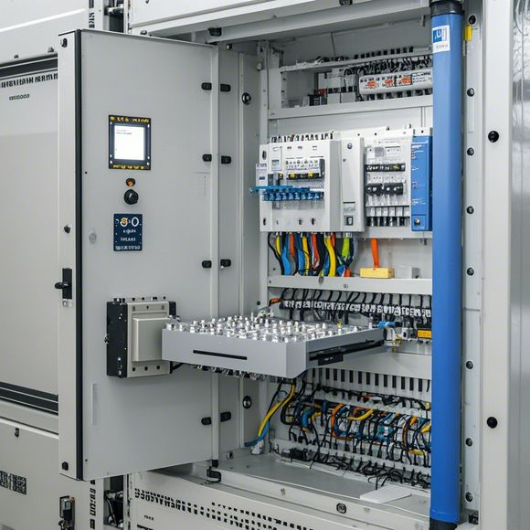
plc输入输出接线图
Sure, based on your provided content, an outline of the PLC input/output wiring diagram could be written as follows:---**Summary:**The PLC (Programmable Logic Controller) is a versatile device used in industrial automation. The purpose of this summary is to provide an overview of the PLC's input and output connections.**Input Connections:**1. **Power Supply:** Typically connected to one or more power sources, ensuring that the PLC operates with sufficient voltage and current.,2. **Sensors:** Connected to sense physical variables such as temperature, pressure, or flow rate. These sensors can provide feedback to control the system's operation.,3. **Controlled Devices:** These are devices controlled by the PLC program, such as motors or actuators. They are typically connected via a dedicated I/O pin or module.**Output Connections:**1. **Motors and Actuators:** These are connected to the PLC to enable it to control physical systems like conveyor belts, pumps, or fans. Output signals are typically sent out through a motor driver circuit or a dedicated relay module.,2. **Displays and Monitoring Devices:** Some PLCs come equipped with built-in displays, which can be used to monitor the status of the system and display data points for easy monitoring.,3. **Communication Links:** For remote access or network connectivity, the PLC may have a communication interface that connects to other devices or systems. This can include Ethernet, Wi-Fi, or other types of communication protocols.In conclusion, the PLC's input and output connections are critical to its functionality. By understanding these connections, you can ensure that the PLC is properly programmed and connected to the system it controls, providing reliable and efficient operation.
"Mastering the Art of PLC Interfacing: A Comprehensive Guide for Effective Connection and Troubleshooting"
Content:
Hello, fellow trade professionals! As you navigate through the complex world of international trade, understanding how to effectively connect your plc (programmable logic controller) to different inputs and outputs is crucial. Today, we are going to dive deep into one of the most important aspects of your operations - PLC interface connection. Whether you're a seasoned trader or a novice, this guide will provide you with the knowledge you need to master this art.
Firstly, let’s talk about what a PLC is – it stands for Programmable Logic Controller. It is a powerful device that can control various industrial processes by executing specific instructions written in a special kind of programming language called Ladder Diagram (LD). This device is designed to be highly efficient, flexible, and reliable.

Now, let's talk about how to connect your PLC to different inputs and outputs. To begin with, the first step is to identify your inputs and outputs. This means understanding what type of signals your system needs to receive or generate. For instance, if your PLC controls a heating system, you might have temperature sensors as inputs, which will send signals to the PLC. On the other hand, if your machine needs to move a part, you would use motion sensors as outputs.
Once you have identified your inputs and outputs, the next step is to determine the appropriate wire types to use for connecting them to your PLC. The choice of wire depends on the voltage level and the type of wiring required. For example, high voltage signals require thicker wires like RG6 or RG58, while low voltage signals use thinner wires like RG213 or RG57.
Next, it’s time to connect your inputs and outputs to your PLC. This usually involves using jumpers or connectors to connect wires together. Make sure you follow the manufacturer's instructions carefully when connecting wires.
Once all connections are made, you need to program your PLC to recognize these inputs and outputs. This process involves writing specific code that tells your PLC what action to take based on the signal received. For example, if your PLC detects a temperature sensor reading higher than the set point, it may automatically adjust the heating system accordingly.

In terms of troubleshooting, there are several common issues that may arise during this process. Firstly, check if all connections are secure and properly grounded. If not, this could cause interference or even damage to your system. Secondly, verify that your inputs and outputs are receiving and sending the correct signals. This may involve testing them manually or using specialized tools such as multimeters. Lastly, if all else fails, seek professional assistance from an experienced engineer who can diagnose and solve any technical problems that arise during setup or operation.
In conclusion, connecting your PLC to different inputs and outputs is a crucial aspect of your trade operations. By following the steps outlined above, you can ensure a smooth and successful integration process. Remember to stay patient and diligent throughout the process, and don't hesitate to reach out for support when needed. Good luck!
Content expansion reading:
Articles related to the knowledge points of this article:
Smart Manufacturing Solutions with PLC Integrated Machinery
PLC Controller for Manufacturing Automation
PLC Programming for Automation Control in the Manufacturing Industry
How to Use a PLC Controller for Your Business
The Role of Programmable Logic Controllers (PLCs) in Foreign Trade Operations
PLC Controllers: A Comprehensive Guide to Understanding Their Prices