PLC Controller Wiring Diagram - A Guide to Connecting and Configuring Your System
This guide will help you connect and configure your PLC controller wiring diagram. It includes step-by-step instructions for connecting wires, configuring settings, and testing your system's functionality. With this guide, you can easily understand how to install and manage the wiring in your PLC system.
In the realm of manufacturing and industrial control, the power of Programmable Logic Controllers (PLCs) is unparalleled. They are masters in the art of automation, enabling systems to perform repetitive tasks with precision, efficiency, and minimal human intervention. To harness the full potential of these marvels of technology, one must first understand the intricate world of PLC controller wiring diagrams.

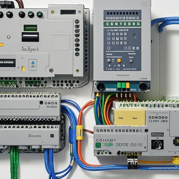
At the heart of any PLC system lies its wiring diagram, a visual representation of how different components come together to form a functional network. This diagram serves as the foundation for ensuring that each component is connected correctly, without missing a wire or mismatched connections. As an experienced PLC operator, it falls upon me to guide you through each step of the process, ensuring that your wiring is not merely functional but also efficient and reliable.
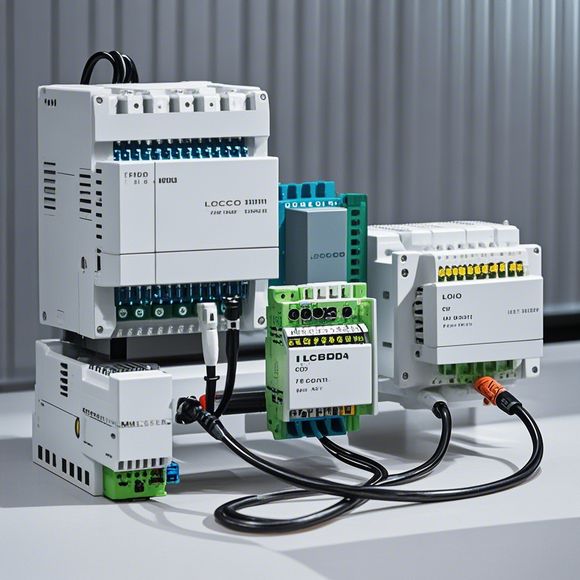
Firstly, let us delve into the basics of a typical PLC wiring diagram. At its core, this diagram consists of three primary components: the input/output modules (I/O modules), the processor unit (CPU unit), and the communication interfaces (CIP). The input/output modules serve as the gateway between the physical world and the digital logic of the PLC. These modules receive data from sensors, actuators, and other devices, converting it into a format that can be processed by the CPU unit.
Next, we have the CPU unit. This is where all the magic happens. It takes in information from the input/output modules, processes it according to predefined algorithms, and sends out commands to the appropriate output modules. The CPU unit is the brain of the PLC, making critical decisions based on incoming data and generating outputs to drive various systems within the plant.
Finally, we encounter communication interfaces such as Ethernet, Profibus, or Modbus. These interfaces enable the PLC to communicate seamlessly with other systems in the factory network, whether they be computers, printers, or other automation devices. By establishing clear protocols and standards for data transmission, these interfaces ensure that the PLC remains responsive and capable of responding to changes in the factory environment.
Now, let us delve deeper into the specific steps involved in connecting these components. First and foremost, it's essential to ensure that all cables used in the wiring are compatible with the PLC model being employed. This means selecting appropriate connectors, cable lengths, and materials based on the specifications of the PLC model you have chosen. Additionally, it's important to follow the manufacturer's guidelines for installing each component, paying particular attention to the placement of connectors and ensuring a clean and secure connection.
Once the hardware is properly installed, it's time to move on to the software side of things. The programming language used for PLC operations will determine the specific commands and functions that need to be programmed into the system. For example, if your PLC is equipped with a PID controller, you would need to write code that adjusts the temperature setpoint based on measured values over time. Similarly, if your PLC is responsible for driving a conveyor belt, you would need to write code that coordinates the movement of goods along the path.

To ensure that your PLC is functioning optimally, it's crucial to conduct regular testing and monitoring. This involves running simulations of various scenarios to verify that the PLC is responding correctly to inputs and producing the desired outputs. You may also need to use specialized tools such as test equipment to measure the speed and accuracy of the system. Additionally, it's important to keep an eye on any errors or warning messages that pop up during operation. Addressing these issues promptly can prevent more serious problems down the line.
Of course, there's no substitute for hands-on experience when it comes to PLC wiring. So, if possible, I highly recommend taking classes or working alongside experienced professionals who can guide you through the process step-by-step. Not only will this give you valuable insights into the inner workings of PLC systems, but it will also help you develop a deeper understanding of the technical challenges faced in modern manufacturing environments.
In conclusion, the world of PLC controller wiring is complex and nuanced, requiring both technical knowledge and practical skills to operate effectively. By following the steps outlined above and staying informed about the latest developments in automation technology, you can become an expert in your own right, confident in the ability to design and manage complex production systems with confidence. Remember, every successful PLC system starts with a well-designed wiring diagram, so take your time in this crucial phase of your career journey.
Content expansion reading:
Articles related to the knowledge points of this article:
The cost of a PLC Controller: A Comprehensive Analysis
PLC Programming for Automation Control in the Manufacturing Industry
How to Use a PLC Controller for Your Business
Plumbers Rule! The Role of PLC Controllers in the World of Waterworks
PLC Controllers: A Comprehensive Guide to Understanding Their Prices