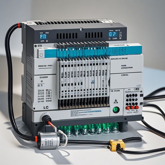
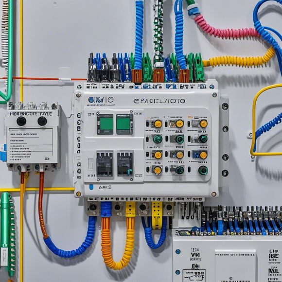
PLC Input-Output Interface Diagram
A programmable logic controller (PLC) is a device used for controlling and monitoring processes, machines, and devices. Its Input-Output Interface Diagram (I/O diagram) is a visual representation of the connections between various components of the PLC, such as sensors, actuators, and processors. This diagram helps in understanding the flow of data between the hardware components and how they interact with each other to perform tasks.The I/O diagram consists of various symbols representing different components of the PLC system. These symbols include input pins, output pins, switches, buttons, sensors, and relays. The input pins represent the signals received from the environment, while the output pins represent the signals sent to the environment. The switches and buttons are used to control the flow of signals, while the sensors and relays are used to monitor and control the environment.An I/O diagram helps in identifying the connections between different components, which can be crucial in troubleshooting and maintenance. It also provides a clear understanding of how the PLC system works, enabling engineers to optimize and improve its performance. Overall, an I/O diagram is an essential tool for any PLC system, providing a comprehensive overview of its functionality and connectivity.
Dear colleagues,
I hope this message finds you in high spirits as we embark on another productive day together. Today, I am excited to bring you a comprehensive discussion on the Input-Output Interface Diagram (IODI) for Programmable Logic Controllers (PLCs). This topic is of paramount importance in the realm of industrial automation, and its mastery can significantly impact the efficiency, reliability, and safety of our manufacturing processes.

At its core, the Input-Output Interface Diagram represents the physical connections between the various components of a PLC system. It serves as the bridge between the PLC's digital inputs and outputs and the external world, ensuring seamless communication and control over critical systems. In essence, it defines the pathway through which data flows from one component to another within the PLC, ultimately leading back to the user interface or the external devices that rely on this information to operate.
Now let's delve deeper into the key components of an Input-Output Interface Diagram. Firstly, we must consider the physical layout of the PLC, which typically involves several modules, each housing a set of inputs and outputs. Each module is connected to other modules through cables or buses, creating a network that extends throughout the entire system. The diagram then maps out the specific connections between these components, indicating where each input or output device is located within the PLC and how they are interconnected.
This connection map not only tells us where things are physically located but also provides vital clues about what type of signal each input or output device produces. For example, if an input device generates a high-impedance signal, we need to ensure that our design allows for a low-current path to flow through this node without causing excessive voltage drops or noise interference. Conversely, if an output device requires a high-voltage signal, we must design the circuitry accordingly to avoid damaging components or compromising safety protocols.
Moreover, understanding the function of each input and output device is crucial for optimizing our PLC design. Some inputs may be used to monitor process conditions in real time, while others may serve as gateways for controlling valves or motors remotely. Similarly, some outputs may be designed to trigger alarms or activate safety systems, while others may be used to send commands to external devices like sensors or printers. By analyzing the purpose and requirements of each component, we can create a more efficient and reliable PLC system that meets the needs of our industry partners and customers.
In addition to its technical significance, the Input-Output Interface Diagram plays a vital role in shaping the overall aesthetics and organization of our PLC hardware. As engineers, designers, and technicians work together to develop this diagram, they must consider factors such as aesthetics, functionality, and ease of use. A well-crafted interface diagram should reflect the intended purpose of each component, highlighting the critical paths and reducing confusion among team members. It should also be visually appealing, with clear labels and arrows pointing to important connections and functions, making it easy for users to understand and interact with the PLC system.

However, creating an effective Input-Output Interface Diagram is no easy task. It requires careful planning, collaboration, and attention to detail. At the outset, we must define our objectives and scope for the diagram. What specific inputs and outputs do we need to capture? What level of detail do we want to include? These questions will help us determine the scope of our design and guide us towards a successful outcome.
Next, we must gather all relevant information about the Input-Output Interface Diagram. This includes drawings, schematics, specifications, and any other documentation that pertains to the design. We must carefully review this material to identify all the connections between different components and to understand their respective purposes. Once we have a solid foundation of knowledge, we can start working on creating our own diagram.
To accomplish this task, we can use various tools and software programs. One popular option is using specialized software such as AutoCAD or Eagle for creating detailed drawings. These programs allow us to easily draw complex shapes, connectors, and wiring diagrams. Additionally, there are many online resources available that provide step-by-step guidance on creating PLC interface diagrams, including tutorials and templates that can help us get started.
As we begin to work on our diagram, it is essential that we maintain a clear mind and focus on the end goal. We must keep in mind that our goal is to create a diagram that accurately reflects the physical connections between the PLC's inputs and outputs, as well as their respective functions and purposes. To achieve this objective, we must remain diligent in our research and analysis, carefully documenting every aspect of our design.
Once we have completed our draft, we must evaluate its accuracy, completeness, and effectiveness. Are all the connections accurately represented? Have we captured all the necessary information? Is the diagram easy to follow and understand? Only by conducting thorough reviews and testing can we ensure that our diagram is both functional and visually appealing. If necessary, we can make revisions to refine our design until it meets our standards.

In conclusion, the Input-Output Interface Diagram is a critical component of any PLC system. Its mastery enables us to effectively communicate, control, and monitor critical processes within our manufacturing environments. By following the guidelines outlined herein, we can create a comprehensive and reliable diagram that informs, inspires, and drives innovation within our teams. Let us commit ourselves to this task with unwavering dedication and expertise, striving to produce the highest quality design possible. Together, we can build a future of productivity, safety, and success in the world of industrial automation.
Content expansion reading:
Articles related to the knowledge points of this article:
Mastering the Art of Plc Controllers: A Comprehensive Guide to Understand and Implement
How to Use a PLC Controller for Your Business
Plumbers Rule! The Role of PLC Controllers in the World of Waterworks
Connecting a PLC Controller to Your Computer
PLC Controllers: A Comprehensive Guide to Understanding Their Prices