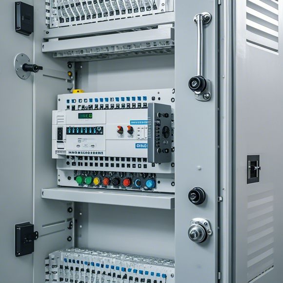
PLC Controller Wiring Diagram in English
Introduction to PLC Controller Wiring Diagram: A Comprehensive Guide
When it comes to controlling industrial processes, one of the most crucial components is the Programmable Logic Controller (PLC). Its ability to automate complex systems with ease and efficiency has revolutionized the manufacturing industry. However, understanding how to connect different devices and components to a PLC controller can seem daunting. This guide will provide a step-by-step walkthrough on how to read and interpret a typical PLC wiring diagram.
Firstly, an understanding of what a PLC controller is and how it works is essential. A PLC is a computer that can be programmed to perform specific tasks based on instructions received from a user interface or other devices connected to it. These devices include switches, sensors, actuators, and more. When these inputs are received by the PLC, it evaluates them according to predefined rules and actions, such as turning on or off a motor, adjusting temperature settings, or even controlling other PLCs within a complex system.

Now let's talk about how to read and interpret a typical PLC wiring diagram. A wiring diagram is a visual representation of the connections between various devices and components within a PLC system. It typically includes lines representing electrical connections, symbols indicating specific functions or devices, and text describing the purpose of each connection. Here are some key points to keep in mind when reading a PLC wiring diagram:
1、Identify the Devices and Components: The first thing you need to do is identify all the devices and components within the PLC system. This includes sensors measuring temperature, pressure, or motion, actuators such as relays or pneumatics, and switches controlling flow or power supply. Once you have identified each device, you can begin to understand their roles within the overall system.
2、Understand the Circuitry: Next, take a look at the circuitry itself. This involves understanding how different devices and components interact with each other. For example, if you have a temperature sensor connected to a PLC, it means that the sensor sends data on the current temperature back to the PLC. The PLC then uses this information to make decisions on how to control other parts of the system, such as adjusting heating elements accordingly.
3、Read the Labels: Many times, the labels on the wiring diagram indicate the purpose of each connection. For example, "IN" indicates a source of power or signal, "OUT" shows where it is being sent, and "ACTUATOR" suggests that there might be a mechanical component involved. By carefully reading these labels, you can quickly determine the intended function of each connection.
4、Follow the Code: If you're working on a project that requires programming or modification of the PLC, it's important to follow the code provided for each connection. Each symbol and number represents a specific function or command within the PLC's program. By understanding these commands, you can easily modify the system to meet your needs.

5、Consult the Manual: Finally, don't hesitate to consult the manual or technical documentation provided by the PLC manufacturer. This will give you detailed information on the specific features and capabilities of each device and component. By doing so, you can ensure that you're connecting everything correctly and that the system is functioning as expected.
In conclusion, reading and interpreting a PLC wiring diagram can seem like a daunting task at first. However, with some practice and patience, anyone can become proficient in this area. By following the steps outlined above and keeping in mind the key points discussed, you'll be able to confidently navigate through any PLC wiring diagram and successfully control your industrial processes.
Content expansion reading:
Articles related to the knowledge points of this article:
Mastering the Art of Plc Controllers: A Comprehensive Guide to Understand and Implement
The cost of a PLC Controller: A Comprehensive Analysis
PLC (Programmable Logic Controller) Control System Basics
Plumbers Rule! The Role of PLC Controllers in the World of Waterworks
The Role of Programmable Logic Controllers (PLCs) in Foreign Trade Operations