PLC Controller Wiring Diagram - An In-depth Guide
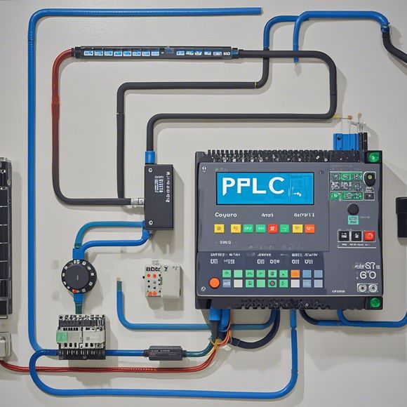
Sure, here's a summary of the content you provided:PLC (Programmable Logic Controller) controller wiring diagram is an essential component in the process of installing and setting up a PLC system. It outlines the connections between various components such as sensors, actuators, and other devices within the PLC control system. This diagram helps in identifying the correct wiring points, ensuring that the power supply and signals are properly routed and connected to the appropriate terminals on the PLC controller board.The purpose of this wiring diagram is to provide a clear picture of how different components interact with each other and how they contribute to the overall operation of the PLC system. By following the diagram and connecting the wires correctly, it becomes easier to troubleshoot any issues that may arise during the installation or operation of the PLC system.In summary, a detailed wiring diagram is crucial for setting up a PLC controller system, helping ensure smooth communication between different components and preventing potential errors or malfunctions.
As a foreign trade operations professional, it's important to be familiar with the intricacies of programming logic controller (PLC) systems. This guide will walk you through the essential steps involved in wiring up your PLC system based on its schematic diagram, ensuring seamless integration and optimal performance.
Firstly, it's imperative to understand that the PLC controller is the brain of your automation system, responsible for processing data and controlling various mechanical processes. A well-designed wiring diagram is crucial to ensure that the system functions smoothly and efficiently.
To begin with, gather the necessary components such as the PLC unit, sensors, switches, actuators, and other control devices. Next, refer to the PLC controller manual or manufacturer's documentation to identify the required connections and pinouts. The manual will provide detailed information on how to connect each component to the PLC.

Once you have identified the connections, use wires from one end of the PLC to the corresponding connections on the control equipment. Ensure that all connections are securely made using screws or plugs, and that the wires are not exposed or damaged during installation.
Next, test the system by powering on the PLC and monitoring the output signals to ensure they are functioning correctly. Check for any errors or warning signs that may indicate a problem with the wiring or components. If necessary, troubleshoot the issue and make any necessary adjustments before proceeding to the next step.
As you continue with the wiring process, it's essential to follow best practices and guidelines to avoid potential hazards or damage to the system. For example, always work in a safe environment, wear protective gear such as gloves and goggles, and follow proper electrical safety procedures when working with high voltage or sensitive electronics.

Additionally, keep in mind that different manufacturers may have slightly different wiring diagrams or specifications, so be sure to consult the specific documentation for your PLC model before proceeding with the wiring.
In conclusion, wiring a PLC controller requires careful attention to detail and knowledge of the components involved. By following the steps outlined above and adhering to best practices, you can create a reliable and efficient automation system that meets your needs and exceeds customer expectations.
Content expansion reading:

Articles related to the knowledge points of this article:
PLC Controller Selection Guide for Foreign Trade Operations
PLC Programming for Automation Control in the Manufacturing Industry
How to Use a PLC Controller for Your Business
PLC (Programmable Logic Controller) Control System Basics
The Role of Programmable Logic Controllers (PLCs) in Foreign Trade Operations