PLC Control Cabinet Wiring Diagram Instructions for Beginners
Sure, here is an example of a summary in English for the PLC Control Cabinet Wiring Diagram for beginners:---"For beginners looking to understand and implement the wiring diagram for their PLC (Programmable Logic Controller), this guide provides clear and concise instructions. Beginners should start by familiarizing themselves with the basic components such as input and output terminals, sensors, and switches that will be connected to their PLC. Then, they can proceed to read the wiring diagram step-by-step, paying attention to the connections made between different components. Once the wiring is complete, it's important to test the system to ensure everything works correctly. This guide aims to simplify the process of connecting and programming the PLC, making it a valuable tool for anyone looking to automate their industrial processes."---
Hello everyone, today I'm going to talk about how to properly wire the PLC control cabinet according to the wiring diagram. As an experienced exporter, I have encountered many customers who are confused about how to connect various components to their PLC control cabinet. Therefore, it is essential for them to understand the basic principles of wiring correctly.
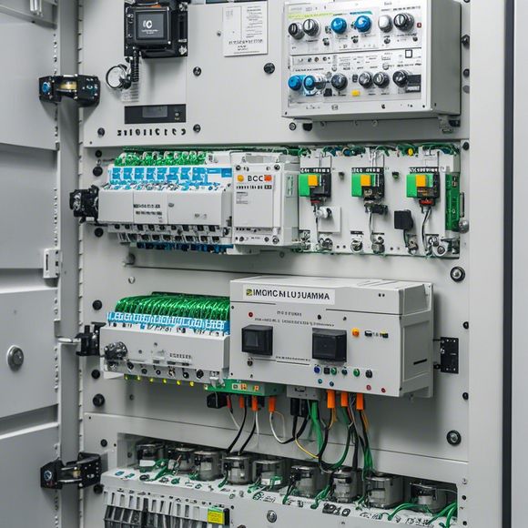
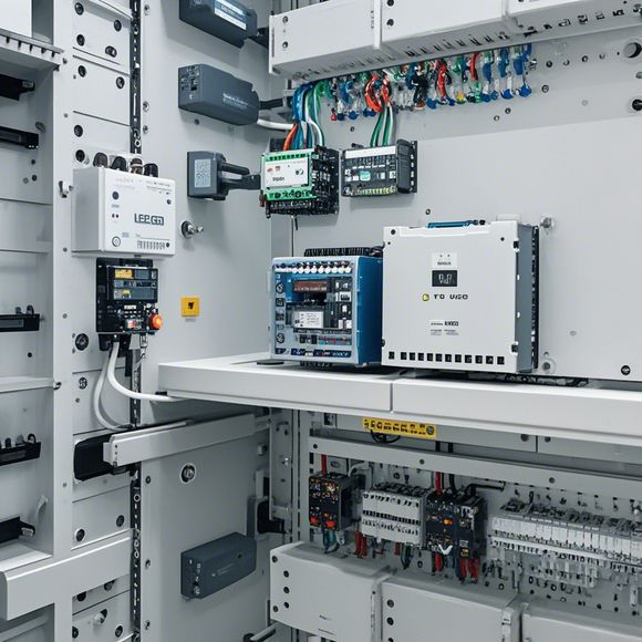
Before we begin, let's first take a look at the general structure of a PLC control cabinet and its key components. A typical PLC (Programmable Logic Controller) control cabinet usually includes several modules such as input devices, output devices, memory, and processor. The input devices are responsible for receiving signals from external sources, while the output devices are used to control various machines and processes based on the commands generated by the processor.
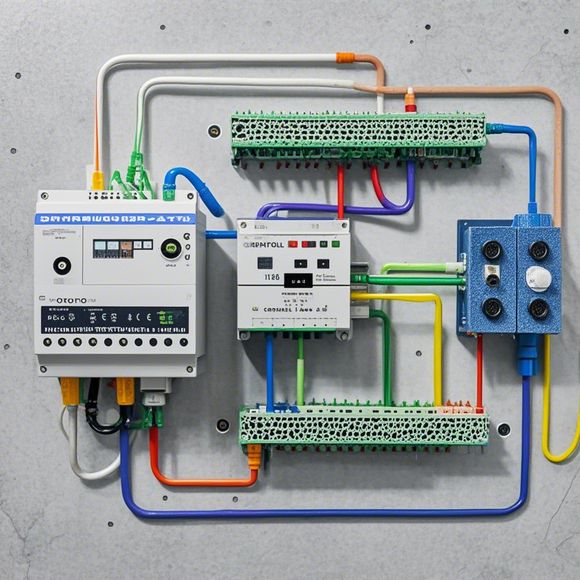
Now, let's move on to the wiring diagram. The wiring diagram typically shows the connections between various components in the control cabinet. It should be noted that different manufacturers may have different symbols and codes, so it is important to refer to the manufacturer's specification when connecting wires.
Firstly, we need to locate the power supply port on the control cabinet, which usually has a plug or socket marked with a symbol indicating its function. Connect the power cord to this port and turn on the power switch.

Next, we need to identify the appropriate input ports for our device. These ports may have specific symbols and numbers indicating their functions. Once you have identified the correct port, connect the appropriate input device to it, ensuring the correct polarity is followed.
After connecting the input devices, you can start configuring the output devices. The output devices usually have multiple pins that represent different functions. For example, one pin may represent the ON/OFF state, another may represent a value, and another may represent a signal. You need to match each pin with the corresponding function on your device and ensure proper polarity.

Once you have successfully connected all the components, you can proceed to test the control cabinet's functionality. Use a multimeter to check if all connections are secure and there are no short circuits. Also, verify that the output devices are working according to the desired specifications.
In conclusion, properly wiring a PLC control cabinet requires a clear understanding of the wiring diagram and the ability to identify different components and their functions. With proper guidance and practice, anyone can successfully connect their PLC control cabinet to any device they require. Remember to always follow the manufacturer's specifications and consult with professionals if needed.

Content expansion reading:
Articles related to the knowledge points of this article:
Smart Manufacturing Solutions with PLC Integrated Machinery
PLC Controller Wiring Guideline
How to Use a PLC Controller for Your Business
PLC (Programmable Logic Controller) Control System Basics
Plumbers Rule! The Role of PLC Controllers in the World of Waterworks