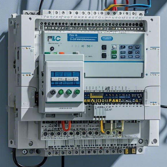
PLC Controller Wiring Diagram Guide
This PLC Controller Wiring Diagram Guide is a comprehensive guide that will help you understand how to connect wires and components within an PLC controller. It provides step-by-step instructions for connecting power supplies, sensors, actuators, and other devices to the PLC controller circuit.The guide covers all the necessary components such as power supplies, sensors, motors, and other devices that can be connected to the PLC controller circuit. It also provides information on how to connect them correctly and safely, including the appropriate connections, voltage requirements, and power ratings.The guide includes diagrams and photos that show the different connections and components that need to be installed. It also provides detailed explanations of each step, making it a useful resource for anyone working with PLC controllers.In summary, this PLC Controller Wiring Diagram Guide is a valuable tool for anyone working with PLC controllers. With its clear instructions and diagrams, it will help you connect wires and components correctly and safely, ensuring that your PLC controller is functioning properly.
Introduction:
Welcome to this comprehensive guide for the plc (programmable logic controller) controller wiring diagram. This manual will assist you in understanding the complexities of connecting different electronic components to your PLC controller. Whether it's installing a new system or upgrading an existing one, this guide provides essential information on how to connect each piece of equipment correctly. Let's dive into the details of the wiring diagram, starting with the fundamental components and proceeding to more advanced topics like programming and troubleshooting.
Basic Components:

The basic components of a PLC controller wiring diagram include the power supply, input/output modules, communication ports, and other necessary devices. The power supply is responsible for delivering electricity to the controller while the input/output modules handle the transfer of signals to and from external sources. Additionally, communication ports enable the PLC to communicate with other systems in the plant or factory floor, while other components such as safety switches and sensors provide real-time feedback for monitoring and control purposes.
Connecting the Power Supply:
The first step in connecting the power supply is ensuring that it meets the specifications of your PLC controller. You must verify that the voltage level and current capacity are appropriate for your device. Next, connect the power supply to the PLC controller by following the manufacturer's instructions. Make sure to connect the positive and negative wires correctly and avoid any cross connections. Finally, test the power supply to ensure it is working properly before moving on to other components.
Installing Input/Output Modules:
After securing the power supply, install the input/output modules that will allow your PLC controller to receive signals from various sources. Each module has specific pinouts and should be connected according to the diagram. Ensure that you have labeled all cables clearly so that they can be easily identified during installation. Test each module individually to confirm that it is functioning properly before integrating it into the overall system.
Communication Ports:
The PLC controller relies on communication ports to interact with other systems in the factory or plant. These ports typically use a standard protocol like Ethernet or PROFINET for data transmission. Connect the communication ports to their respective ports on the PLC controller, following the manufacturer's instructions carefully. Test each connection to ensure that data flows smoothly between the two units.
Other Components:
As your system grows, you may need to incorporate additional components such as safety switches, sensors, or actuators. Each component has its own unique wiring requirements, so it's crucial to consult the manual for each one before connecting them to the PLC controller. For safety switches, make sure they are properly rated for the load they will handle and follow the manufacturer's instructions for connecting them to the PLC controller. Additionally, sensors and actuators should have their own dedicated connections, so be sure to label and route each cable correctly.

Programming and Programming Tools:
Once the wiring is complete, it's time to program your PLC controller. This involves writing software code that enables the controller to interpret inputs from sensors and actuate valves or motors based on the commands received. There are various programming tools available that can help you automate tasks and optimize production processes. Choose a tool that best suits your needs and familiarize yourself with its interface before beginning the coding process.
Troubleshooting and Maintenance:
While installing and programming your PLC controller, you may encounter issues that need to be resolved. Be prepared to troubleshoot common problems such as incorrect connections or faulty components. Keep a record of what worked and what didn't during each installation process for future reference. Additionally, regular maintenance is key to keeping your PLC controller functioning at its best. This includes checking for dust buildup, ensuring proper temperature and humidity levels, and performing periodic software updates.
Conclusion:
In conclusion, connecting a PLC controller to your system requires careful attention to detail and knowledge of the various components involved. With proper wiring diagrams and a solid understanding of each component's function, you can create a robust and efficient automation system. Remember to follow manufacturer's guidelines, test everything thoroughly, and maintain your PLC controller regularly for optimal performance. Happy coding!
Content expansion reading:
Articles related to the knowledge points of this article:
PLC Controller Wiring Guideline
The cost of a PLC Controller: A Comprehensive Analysis
The Role of Programmable Logic Controllers (PLCs) in Foreign Trade Operations
PLC Controllers: A Comprehensive Guide to Understanding Their Prices