plc控制柜接线图讲解
Sure, I can provide you with a brief overview of a PID controller cabinet wiring diagram. A PID controller is a type of feedback control system that uses three components: the Proportional (P), Integral (I) and Derivative (D) terms to adjust its output signal based on the error between the desired value and the actual output value.Here's a simple schematic of how these components might be connected in a PID controller cabinet:``,+-----------------+,| |,| Controller |,| |,| |,| |,+-----------------+,``The P component is responsible for responding to changes in the error directly. It's calculated as an average value of the current error over time. The I component represents the integral of the error over time. It's calculated by summing all past errors, weighted by their duration. Finally, the D component represents the rate of change of the error, which is the derivative of the error with respect to time.To complete the PID controller cabinet, you'll need to wire the sensors and actuators to the respective inputs and outputs of the controller. You can then program the controller software to adjust the P, I, and D values based on the sensor readings and desired output values.Remember, each application may require specific adjustments to the PID parameters and configuration, so it's important to consult your manufacturer's manual or hire a professional engineer for more tailored advice.Introduction to PLC Control Cabinet Wiring Diagrams

Content:
Hello everyone, today we're going to delve into the fascinating world of PLC (Programmable Logic Controller) control cabinets. These are essential components in modern industrial setups, enabling precise and efficient automation of processes through their sophisticated programming capabilities.
Let's start with a basic understanding of what a PLC is all about. A PLC (Programmable Logic Controller) is a computerized device that can be programmed to perform a specific task or sequence of tasks. Unlike traditional mechanical controllers, PLCs are highly flexible and can adapt to changing conditions and requirements. They work by storing information in memory and using it to execute instructions based on predefined rules.
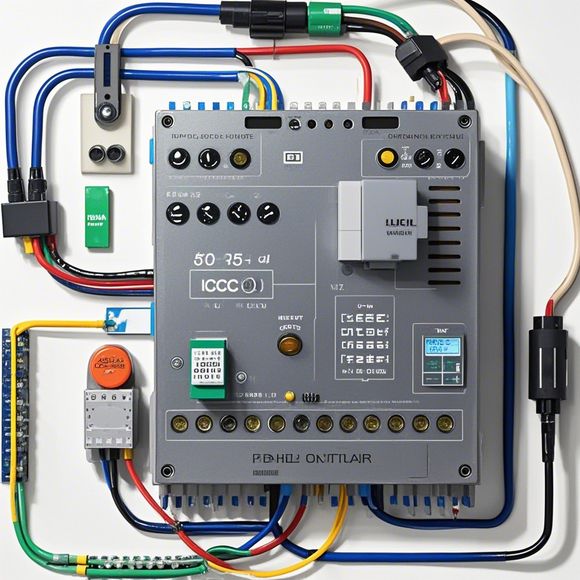
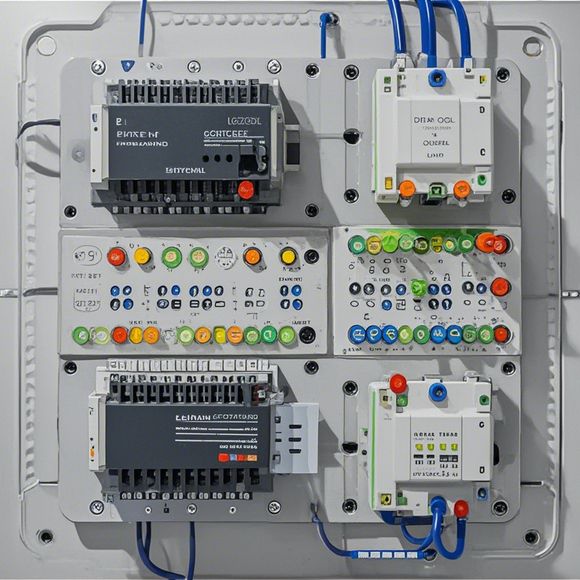
Now let's talk about the importance of wiring diagrams in PLC control cabinets. A wiring diagram is an essential tool that shows how different wires and components are connected in a particular system. It helps engineers and technicians to understand the circuitry and ensure that everything is working correctly.
Here is how we can use wiring diagrams to understand a typical PLC control cabinet:
1、Reading the Diagram: The first step is to read the wiring diagram carefully. Pay attention to the colors used, which often indicate whether a wire is live or grounded. You will also notice the various components such as relays, sensors, and switches that are connected together.
2、Identifying Components: In the diagram, you will see labels indicating different components like sensors, motors, relays, etc. This helps you understand the purpose of each component in the overall system.

3、Mapping Out Circuitry: Once you have identified the components, you need to map out the circuitry. This involves connecting the wires according to the diagram, ensuring that all components are properly interconnected and that no redundant connections are made.
4、Testing: After completing the wiring, it's important to test the circuitry. This involves checking for any short circuits or open connections that could lead to safety hazards. If there are any issues, you need to make necessary adjustments and retest until everything works perfectly.
5、Documentation: Finally, it's crucial to document your work. Keep track of the connections made during the wiring process and update the wiring diagram as per your changes. This will help others working on the project to understand how the system works and avoid confusion later on.
In conclusion, understanding the wiring diagram of a PLC control cabinet is vital for ensuring the proper functioning of the system. By following these steps, you will be able to identify components, create circuits, and test them effectively. Remember to always prioritize safety during this process and keep documentation for future reference.
Content expansion reading:
Articles related to the knowledge points of this article:
The cost of a PLC Controller: A Comprehensive Analysis
PLC Programming for Automation Control in the Manufacturing Industry
How to Use a PLC Controller for Your Business
PLC (Programmable Logic Controller) Control System Basics
Plumbers Rule! The Role of PLC Controllers in the World of Waterworks
The Role of Programmable Logic Controllers (PLCs) in Foreign Trade Operations