PLC Controller Wiring Diagram
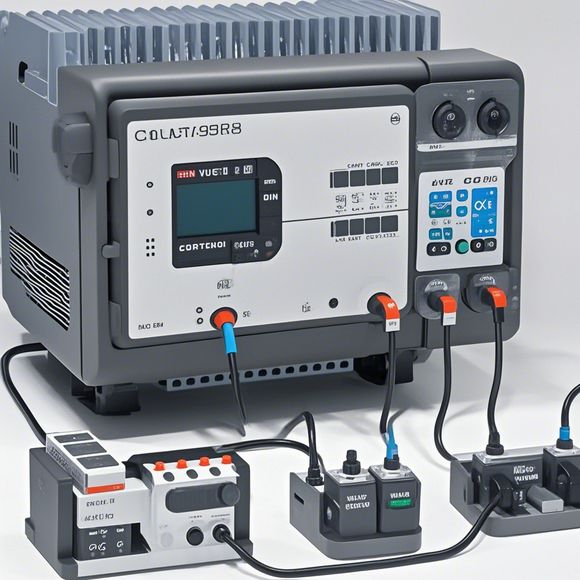
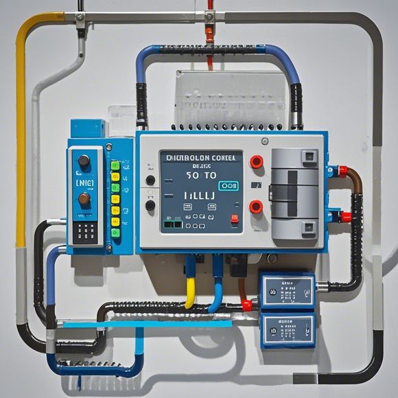
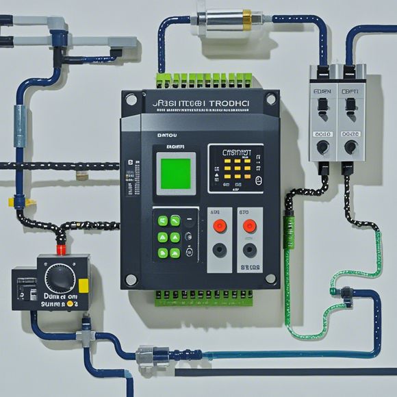
Sure, here's a brief summary of the content in your request:"The PLC Controller Wiring Diagram illustrates how electrical wiring connects various components to the Programmable Logic Controller (PLC). The diagram typically shows the input and output connections for sensors, actuators, relays, and other electronic devices. The wiring diagram helps engineers understand the flow of power and data between these components and ensures that the PLC operates correctly. It also provides a reference for troubleshooting and maintenance."
In the realm of international trade, understanding how to operate and troubleshoot your PLC (Programmable Logic Controller) is crucial for ensuring smooth operations. A well-maintained plc controller can significantly enhance productivity and efficiency in industrial settings. The intricate wiring diagram that accompanies your controller serves as a vital reference guide, outlining the connections between various components within your manufacturing or control system.

The first step in any electrical project is familiarizing yourself with your plc's wiring diagram. It's like having a roadmap, showing you where to start and which wires to work on. This map is essential for understanding the flow of power and data within your system, allowing you to identify potential issues early on.
Once you understand the basics, it's time to delve deeper into the specifics of each component. For example, if your controller has a motor driver integrated into its design, you'll need to understand how this driver communicates with the motor and controls it. The same goes for sensors and other input devices that provide feedback on the status of your process.
As you work through the wiring diagram, pay attention to the colors and symbols used to denote different components and their function. These visual aids can make complex connections easier to understand. For example, red wires are typically used for power, blue represents grounding, and green often indicates signal lines or control signals. Knowing these color codes can help you avoid confusion during installation.

When working with electrical components, safety should always be a top priority. Always wear protective gear such as gloves and eyewear, and ensure that all tools and equipment are properly grounded before use. Additionally, follow the manufacturer's instructions carefully when connecting wires and installing components, as errors can lead to serious safety hazards.
Another important aspect of working with plc controllers is troubleshooting. If you encounter issues such as circuit failures or programming errors, refer back to your wiring diagram to identify the cause. This can involve testing specific components or checking for loose connections. Remember, patience and persistence are key when troubleshooting complex systems like your PLC.
In summary, mastering the art of operating and troubleshooting PLC controllers requires a deep understanding of the wiring diagram and the associated components. By following the steps outlined above, you'll be well on your way to ensuring the success of your industrial projects. Remember, investing in quality electrical hardware and maintaining regular maintenance practices will go a long way in achieving reliable and efficient results.

Content expansion reading:
Articles related to the knowledge points of this article:
Smart Manufacturing Solutions with PLC Integrated Machinery
PLC Controller Selection Guide for Foreign Trade Operations
How to Use a PLC Controller for Your Business
Plumbers Rule! The Role of PLC Controllers in the World of Waterworks
The Role of Programmable Logic Controllers (PLCs) in Foreign Trade Operations