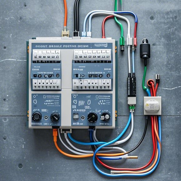
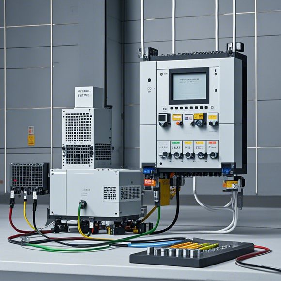
PLC Input/Output Interface Diagram
Certainly! Here's a summary in English for the PLC (Programmable Logic Controller) Input/Output Interface Diagram:The Programmable Logic Controller (PLC) is an important device used in industrial automation, allowing for the control of various machines and systems. Its primary interface is the Input/Output (I/O) Interface Diagram, which is a diagram that represents the electrical connections between the PLC and the devices it controls.This diagram consists of several components, including input modules, output modules, and communication modules. The input modules receive signals from various sensors and actuators, while the output modules send signals to control the devices they are connected to. Communication modules facilitate the transfer of data between the PLC and other devices or computers.The I/O Interface Diagram is essential for ensuring proper communication between the PLC and its controlled systems, as well as providing a clear understanding of the devices involved in the automation process. By using a diagram, you can quickly identify any issues with the connection or communication between devices and make necessary adjustments.
As an experienced exporter, I've seen my fair share of challenges when it comes to connecting and operating industrial control systems, like Programmable Logic Controllers (PLCs). One of the most critical aspects is ensuring that the Input/Output (I/O) connections are properly wired and tested. This ensures smooth functioning and reliable data exchange between the PLC and various components within the production line or other automation system. In this guide, we’ll dive into the essential aspects of wiring the Input/Output interface on a programmable logic controller (PLC).

To start with, the first step in any wiring endeavor is to have a clear understanding of the layout of your PLC's hardware. Your manual will provide a detailed diagram of all the input and output devices connected to the PLC. It’s crucial to pay attention to each pin assignment and ensure they match up with the actual physical connections.
Once you have the manual in hand, it’s time to gather the tools and equipment required for the job. You'll need a multi-meter with a high-current capability to measure the current flow through the wires, a crimping tool to connect the wires securely, and a set of screwdrivers to install and remove the terminal blocks where the wiring goes.
The next step involves identifying the appropriate wires for each connection. For example, if your PLC has multiple inputs that need to be connected to different sensors, you'll want to use color-coded wires for easy identification. Similarly, if there are several outputs that control motors or lights, you'll need to use colored wires to distinguish between them.
Once you have identified the wires, begin by unscrewing the terminal block from the back of the PLC. Make sure to leave enough space around the screw so that you don't damage the circuitry inside the PLC. Next, carefully remove the old terminal blocks and replace them with new ones. Be careful not to damage the wires as you work.

With the terminal blocks in place, it's time to connect the wires to each device. Start by attaching each wire to a corresponding terminal block on the PLC. Make sure to follow the manufacturer's instructions carefully, as improper connections can lead to electrical problems later on.
Once all the wires have been attached to their respective terminal blocks, it's time to connect them together using crimping tools. This process is important because it secures the wires in place and prevents future short circuits. Make sure to follow the manufacturer's guidelines for crimping tools and techniques.
Once all the wires have been connected securely, it’s time to test the Input/Output interface. Use a multi-meter with a high-current setting to check the resistance of each connection point. If the reading is too high or too low, it may indicate an issue with the connection or the wiring itself. Take the necessary action to correct the issue before moving on.
In addition to testing for proper connections, it's also important to check for any visible signs of wear or damage on the wires themselves. If you notice anything unusual, such as discoloration or frayed edges, it may be necessary to replace the wires altogether.

Finally, once everything has been tested and checked out, it’s time to label each terminal block clearly indicating what type of device it connects to. This will make it easier to identify and troubleshoot any issues down the road.
In conclusion, connecting and operating an industrial control system like a programmable logic controller (PLC) requires careful planning and attention to detail. By following these simple steps and taking the necessary precautions, you can ensure that your Input/Output interface is functioning properly and efficiently. Don’t forget to consult the manufacturer’s manual for specific guidance on how to connect each component and wire accordingly. With patience and practice, you’ll be able to handle any challenges that come your way in the world of exporting and manufacturing.
Content expansion reading:
Articles related to the knowledge points of this article:
PLC Controller Selection Guide for Foreign Trade Operations
PLC Controller for Manufacturing Automation
How to Use a PLC Controller for Your Business
PLC (Programmable Logic Controller) Control System Basics
Plumbers Rule! The Role of PLC Controllers in the World of Waterworks
The Role of Programmable Logic Controllers (PLCs) in Foreign Trade Operations