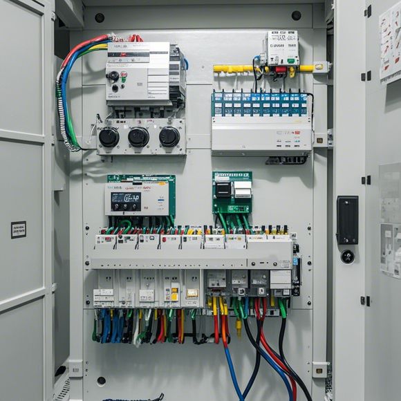
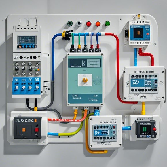
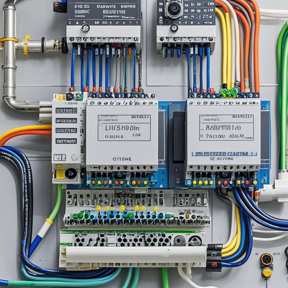
PLC Controller Connection Diagram: A Guide to Connecting and Troubleshooting
This is a guide on how to connect and troubleshoot PLC controller connections. Firstly, you need to understand the basics of PLC controllers and their connections. Then, you should follow the diagram provided in the manual or instructional guide to properly connect each component. It's important to ensure that all connections are secure and properly labeled. Once the connections are made, you can begin troubleshooting any issues that arise. If you encounter problems, refer back to the connections diagram to identify where the issue may be located. With proper knowledge and care, you can successfully connect and troubleshoot your PLC controller.
Introduction:
Hello everyone, today we are going to talk about the PID controller connection diagram. As an experienced trader and a professional in the field of automation, it's essential to know how to connect and troubleshoot the PLC controller. In this guide, we will provide you with all the necessary information to ensure that your PLC system is functioning smoothly and efficiently. So let's get started!
1、Understanding the PID (Proportional-Integral-Derivative) Controller
The PID controller is a popular type of feedback control loop used in many applications, including manufacturing, process control, and industrial automation. It consists of three main parts:

a. Proportional: This part calculates the error between the current value and the desired value. It gives a direct signal to adjust the output based on the error.
b. Integral: This part accumulates the error over time. It smooths out any sudden changes in the desired value and provides a more stable signal for adjustment.
c. Derivative: This part measures the rate of change of the error. It gives a signal to adjust the output faster than the integral part. This helps to prevent the system from oscillating around the setpoint due to small disturbances.
2、The Basic Components of the PID Controller
The basic components of a PID controller are:
a. Input Sensor: This component receives the actual output value from the process and compares it with the desired output value. It sends this comparison to the PID controller.
b. Output Actuator: This component generates the control signal that drives the actuator or motor. It receives the signal from the PID controller and applies it to the actuator accordingly.
c. Control Algorithm: This is a software routine that determines how to adjust the control signal based on the input signal from the sensor. It combines the proportional, integral, and derivative signals to create the final control signal.
d. PLC (Programmable Logic Controller): This is a digital computerized system that controls the logic flow and execution of instructions. It is responsible for receiving commands from the control algorithm, processing them according to its predefined rules, and generating appropriate output signals for the actuators.

3、Connecting the PID Controller to the PLC
To connect the PID controller to the PLC, you need to perform the following steps:
a. Identify the required inputs and outputs: Determine which sensors, actuators, and other devices you need to interface with your PLC. This will help you understand what type of hardware you need to connect.
b. Choose the appropriate PID controller module: There are several options available for PID controllers, depending on your requirements and budget. Some popular choices include Honeywell, Allen-Bradley, and Siemens S7-300 series.
c. Connect the PID controller to the PLC: Once you have selected your PID controller module, connect it to your PLC using appropriate wiring and cabling. Ensure that all connections are secure and tight.
d. Set up the PID controller configuration: Use the PLC programming language (e.g., Ladder Diagram, Function Block Diagram, or Programmer) to configure the PID parameters. You can use built-in features or custom functions to adjust the gains, time constants, and other parameters.
e. Test the PID controller functionality: After configuring the PID controller, test it by connecting it to a simulation device or real-world application. Check if the output signal matches the expected values. Make any necessary adjustments and ensure that the PID controller is functioning correctly.
4、Troubleshooting Common Issues with PID Controllers
While working with PID controllers, you may encounter some common issues such as:

a. Slow Response Time: If your PID controller takes too long to respond to changes in the process, there could be issues with its internal circuitry or external connections. Check your wiring and ensure that all connections are secure and tight.
b. High Overshoot: If the output signal goes above or below the desired setpoint too quickly, it means that there is an excessive gain in the PID controller. Try adjusting the gains or adding a dampening factor to limit the overshoot.
c. Oscillations: Oscillations occur when the PID controller gets stuck in an unstable state. To prevent this, add a reset signal or use a deadband to limit the output signal's amplitude.
d. Noise or Interference: Noise or interference from external sources can cause errors in the PID controller. Use shielded cables or optoisolators to protect the signal from external interference.
e. Poor Sensitivity: If the PID controller is not sensitive enough to detect small changes in the process, you may need to increase its sensitivity settings or add additional sensors to improve its performance.
5、Conclusion
In conclusion, connecting and troubleshooting a PID controller is an essential skill for anyone involved in automation and process control. By following these guidelines and troubleshooting common issues, you can ensure that your PLC system is functioning properly and effectively. Remember to always keep learning and exploring new technologies as automation continues to evolve and expand across industries. Thank you for listening and have a great day!
Content expansion reading:
Articles related to the knowledge points of this article:
PLC Controller Wiring Guideline
PLC Programming for Automation Control in the Manufacturing Industry
How to Use a PLC Controller for Your Business
PLC (Programmable Logic Controller) Control System Basics
PLC Controllers: A Comprehensive Guide to Understanding Their Prices