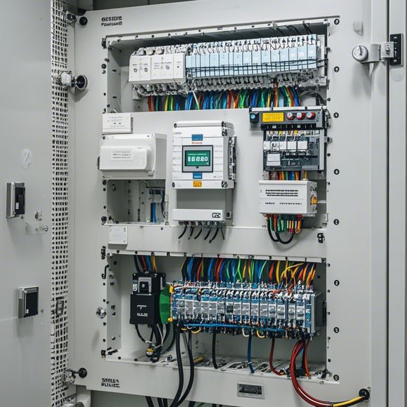
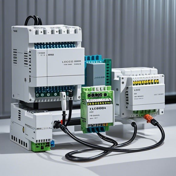
PLC Controller Wiring Diagram
The PLC (Programmable Logic Controller) controller wiring diagram is a detailed representation of the electrical connections between various components within a control system. It typically includes symbols and lines indicating wires, terminal blocks, sensors, actuators, and other hardware devices. The wiring diagram helps in understanding how the different parts of the system interact with each other and how data is transmitted from sensors to processors for processing and then to motors or other actuators for control.In this context, "PLC" refers specifically to Programmable Logic Controllers, which are designed to autonomously control industrial processes by processing information received from sensors. These controllers can handle complex algorithms and perform tasks such as sequencing, monitoring, and adjusting process variables to maintain optimal conditions.To summarize, an PLC controller wiring diagram provides essential information about the electrical connections within an industrial control system, enabling engineers to design, install, and maintain the system effectively.
As a foreign trade operator, understanding the intricacies of our industry requires familiarity with various aspects, including the wiring diagram for our PLC (Programmable Logic Controller) controller. This document serves as a comprehensive guide that outlines the essential components and connections required to ensure seamless operation of our automation systems.
At the heart of this process lies the PLC controller, which is the brain of the automation system. It is responsible for interpreting commands from external devices and executing them accordingly. The wiring diagram for our PLC controller provides a visual representation of how different components are interconnected, enabling us to understand the workings of our system better.

To begin with, let's examine the main components involved in our PLC controller. These include the CPU (Central Processing Unit), which handles the processing of data and commands; the RAM (Random Access Memory), where temporary variables used in calculations are stored; the ROM (Read-Only Memory), which stores firmware programs; and the input/output interface, which connects external devices such as sensors, motors, and other control devices.
Now, let's move on to the wiring diagram. It consists of several sections, each representing a specific connection between the components mentioned above. For example, the CPU is connected to the ROM through a dedicated bus, which allows for quick access to stored programs. The RAM is also linked to the CPU through a memory bus, enabling it to store and retrieve data quickly. The I/O interface, on the other hand, is responsible for receiving input signals from external devices and sending output signals to control devices such as actuators.
In addition to these components, there are also some key connections that need to be established. For instance, the power supply is connected to the CPU through a dedicated power bus, ensuring that it receives sufficient voltage and current to function properly. The grounding connection is also crucial for maintaining safety in our system, as it helps prevent electrical short circuits and potential hazards.
Now that we have a basic understanding of the wiring diagram, let's discuss some practical applications that can benefit from this knowledge. One common scenario involves the integration of PLCs into industrial processes. In this case, we need to ensure that the CPU communicates with the appropriate sensors and actuators, while also managing their respective output signals. By carefully following the wiring diagram, we can avoid errors and ensure optimal performance of our system.
Another important aspect of our work is error handling. PLC controllers are often used in critical applications where even minor errors can have serious consequences. Therefore, it is essential to understand how the wiring diagram can help us identify and troubleshoot issues quickly. For example, if a sensor fails to provide accurate readings, we can trace the fault back to the I/O interface and make necessary adjustments to improve performance.

Finally, let's consider some potential challenges associated with using our PLC controllers. One common issue is network connectivity, which can lead to communication problems between different components. To address this issue, we can use reliable network protocols such as Ethernet or Modbus, ensuring that data transfer is smooth and consistent. Another challenge is software compatibility, which can cause mismatches between different versions of our PLC controllers. By keeping track of updates and patches, we can minimize this risk and ensure optimal performance.
In conclusion, understanding the wiring diagram for our PLC controller is crucial for maintaining and enhancing the efficiency of our automation systems. By following best practices and staying up-to-date on the latest developments in the industry, we can ensure that our systems remain reliable, secure, and productive. So next time you encounter any challenges related to your PLC controller, don't be afraid to refer to this wiring diagram and seek out the expertise of a professional who can guide you through the process step by step.
Content expansion reading:
Articles related to the knowledge points of this article:
PLC Controller for Manufacturing Automation
PLC Programming for Automation Control in the Manufacturing Industry
How to Use a PLC Controller for Your Business
PLC (Programmable Logic Controller) Control System Basics
Plumbers Rule! The Role of PLC Controllers in the World of Waterworks
The Role of Programmable Logic Controllers (PLCs) in Foreign Trade Operations