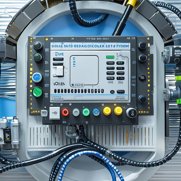
PLC Controller Wiring Guide
As a foreign trade operator, it is crucial to have a comprehensive understanding of the wiring requirements for your plc (programmable logic controller) system. A well-written manual can save time and money in the long run, especially when dealing with complex systems that require multiple components to work together seamlessly. In this guide, we will provide you with an easy-to-follow step-by-step approach to properly connect the various wires between your plc controller and the other devices on the network.
Firstly, ensure that all the electrical components used in your wiring are compatible with each other. This includes ensuring that the voltage and current required by each component match the specifications of your plc controller. Additionally, check whether the wiring materials are suitable for the temperature range and environment your system operates in.

Secondly, begin by laying out a basic layout of the wiring diagram, which should include all the necessary connections between the plc controller, input/output modules, sensors, actuators, and other components on the network. Ensure that all components are labeled clearly and that there is enough space between each connection point to avoid overcrowding.
Next, connect the power supply cable from the power source to the plc controller. Make sure that the correct terminals are connected to each component and that there are no exposed or loose connections. Once the power supply is securely connected, test the entire circuit to ensure that all components are functioning correctly and that there are no short circuits or faults.
Now, move onto connecting the input/output cables between the plc controller and the other components on the network. Start by connecting the input/output cable to the appropriate port on the plc controller. Make sure that the correct type of connector is used for each connection point and that the cables are firmly plugged into the port without any gaps or loose ends.

Once the input/output cables are connected, connect the sensors and actuators to their corresponding ports on the plc controller. Make sure that the connections are secure and that there is no interference between different components. Test the system again to ensure that all sensors and actuators are working correctly and that there are no obstructions preventing communication.
Finally, verify that all connections between the plc controller and other components are secure and that there are no exposed wires or loose connections. Check for any signs of corrosion or damage to the wiring materials and replace any damaged components as needed.
In conclusion, properly connecting the wires between your plc controller and other components on the network requires careful planning and attention to detail. By following these simple steps, you can ensure that your system is safe, reliable, and efficient. Remember to consult with professionals if you need assistance with more complex wiring projects or if you encounter any issues during the installation process.

Content expansion reading:
Articles related to the knowledge points of this article:
PLC Controller for Manufacturing Automation
PLC Programming for Automation Control in the Manufacturing Industry
How to Use a PLC Controller for Your Business
PLC (Programmable Logic Controller) Control System Basics
Plumbers Rule! The Role of PLC Controllers in the World of Waterworks
The Role of Programmable Logic Controllers (PLCs) in Foreign Trade Operations