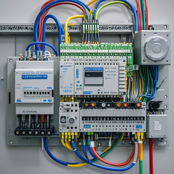
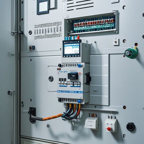
PLC Wiring Guide for Beginners
"The PLC Wiring Guide for Beginners" is a guide that provides basic knowledge on how to wire a Programmable Logic Controller (PLC). It explains the different parts of a PLC, such as the CPU, input and output modules, and communication interfaces. The guide also covers common wiring tasks, such as connecting sensors, motors, and switches to the PLC. Additionally, it discusses safety precautions when working with electrical systems, including grounding and power sources. Overall, this guide provides a useful resource for beginners looking to learn how to install and configure a PLC system.
Introduction:
Hello everyone, today I will be showing you how to wire up a PLC (Programmable Logic Controller) for your industrial automation needs. This guide is designed for beginners who are new to this field. So let's get started!
Step 1: Gather Your Components
Before we start, make sure you have all the necessary tools and materials required for the job. You will need an electrical drill with a Phillips head screwdriver, wire strippers, wire nuts, and a multi-meter to measure voltage and current. Also, ensure you have the correct type of wire for each connection point.

Step 2: Connect the Cables
The first step in wiring up the PLC is to connect the cables to the appropriate terminals on both sides of the controller. Start by identifying the terminals on the front and back panels of the PLC. These terminals are usually labeled with letters or numbers.
For example, if the terminals on the front panel are labeled "A," "B," and "C," then your wires should be connected from the "A" terminal on the front panel to the corresponding "A" terminal on the back panel, and so on. Make sure that all wires are securely connected to their respective terminals without any loose ends.
Step 3: Connect the Power Source
Once you have connected all the wires correctly, it's time to power up the PLC. Turn off all other devices and unplug the power outlet before connecting the PLC to the power source. Use the electrical drill to remove the screws holding the power supply unit in place.

Next, locate the positive (+) and negative (-) terminals on the power supply unit and connect them to the corresponding terminals on the PLC. Be careful not to cross over or connect the wrong wires. Once you have connected both wires correctly, turn on the power supply unit and monitor the LED indicators to confirm that everything is working properly.
Step 4: Connect the Control Panels
Now that you have connected the power supply unit, it's time to connect the control panels to the PLC. Again, identify the control panel ports and label them as you did during step 2. Connect the wires from the control panels to the appropriate ports on the PLC.
For example, if the control panels have ports marked "L1," "L2," and "L3," then connect the wires from these ports to the corresponding ports on the PLC. Ensure that all connections are secure and no loose ends remain.
Step 5: Test and Verify

After completing all the wiring connections, test the PLC system to verify that everything is working properly. Use a multi-meter to check the voltage and current readings at different points throughout the circuit. If any issues arise, troubleshoot and adjust the connections accordingly.
Conclusion:
In conclusion, successfully wiring up a PLC can seem like a daunting task, but by following these steps and using proper equipment, it becomes much easier. Remember that safety should always come first when working with electrical components. Good luck with your PLC installation!
Content expansion reading:
Articles related to the knowledge points of this article:
Smart Manufacturing Solutions with PLC Integrated Machinery
How to Use a PLC Controller for Your Business
PLC Controllers: A Comprehensive Guide to Understanding Their Prices
Effective Strategies for Handling PLC Control System Faults
PLC Controller Advantages: A Comprehensive Guide for Success in Global Trade
PLC Controllers in Global Commerce: An Insight into Their Role in Managing Industrial Processes