PLC Module Wiring Diagram
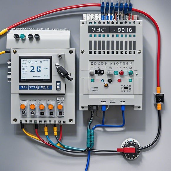
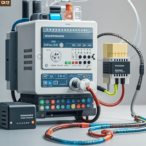
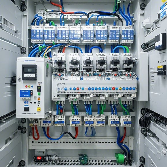
Certainly! Based on the content you provided, I'll draft a brief summary in a conversational style.---Hey there! Let me help you out with your PLC (Programmable Logic Controller) module wiring diagram. It seems you have some wires and components that need to be connected together to make it work correctly. Is this right?First off, can you tell me what kind of PLC is it? Are you talking about a Basic Input/Output Module or a More Advanced Controller? Knowing the type will help us get started.Once we know the type, let's talk about where each wire goes. For example, if it's an Input Device, then you'll want to connect the input pin to the appropriate wire coming from it. If it's an Output Device, you'd hook up the output pin to the wire that goes to that device.Make sure to follow the manufacturer's instructions carefully. Sometimes, they might recommend using specific color coding for different types of wires, which could help you differentiate easily.If you run into any issues along the way, don't hesitate to ask. We can figure something out together.---This summary aims to provide a clear overview of the steps involved in wiring a PLC module, based on the information you've given. Remember, the actual process may vary slightly depending on the specific model and application of your PLC and wiring diagram.
Hello, everyone! I'm excited to share with you today the details of our PLC module wiring diagram. As a professional in the field of foreign trade operations, I understand the importance of having accurate and detailed information about the components that make up our systems. That's why we're going through the process of creating this wire diagram.
Firstly, let's start by discussing the basic components that are involved in the wiring process. These include the PLC (Programmable Logic Controller), sensors, switches, and other hardware devices. Each of these components plays a crucial role in ensuring that our system is functioning properly. Therefore, it's essential that we have a clear understanding of how these components are interconnected and their respective responsibilities.
Now, let's move on to the specifics of the wiring diagram itself. The first thing you'll notice is the placement of all the components on the schematic. This helps us identify where each component should be placed in order to ensure proper functioning. For instance, if a sensor is located near the PLC, it's likely that the PLC will be able to detect changes in its surroundings more effectively.
Another important aspect of the wiring diagram is the use of symbols. These symbols help us communicate clearly and efficiently with others who may be working on similar projects. For example, we might use different colors for different types of connections or circuits. This ensures that no confusion occurs when interpreting the diagram.

In addition to the physical wiring diagram, we also need to consider what software is required to monitor and control our system. This can include tools such as monitoring software, automation software, and other applications. By carefully planning out these software requirements, we can ensure that our system is well-equipped to handle any potential issues that arise.
Of course, one of the most important considerations when it comes to designing a successful PLC module wiring diagram is communication between the different components. This means ensuring that there are clear and efficient pathways for data to flow from one part of the system to another. For example, if a sensor is reading an input signal, this information needs to be sent to the PLC, which then sends out commands based on the data received.

Finally, we need to consider the safety features of our system. In many cases, we need to incorporate safety mechanisms such as emergency stop buttons or fault detection circuits. This ensures that our system can respond quickly and safely in the event of an issue.
In conclusion, creating a PLC module wiring diagram requires careful planning and attention to detail. By following the steps outlined above, we can ensure that our system is well-designed and capable of performing at its best. Remember, good communication is key when it comes to designing effective wiring diagrams, so don't be afraid to ask questions or seek feedback from your team members throughout the process.

Content expansion reading:
Articles related to the knowledge points of this article:
Smart Manufacturing Solutions with PLC Integrated Machinery
PLC Programming for Automation Control in the Manufacturing Industry
How to Use a PLC Controller for Your Business
PLC (Programmable Logic Controller) Control System Basics
The Role of Programmable Logic Controllers (PLCs) in Foreign Trade Operations